Locations for child seats secured using the seat belt
This table indicates the options for Installing child seats secured using the seat belt and universally approved in relation to the weight of the child and the seat in the vehicle.

Your new energy vehicle is integrated with advanced technologies, safety, environmental protection and economy.
This manual provides necessary information to help you drive your vehicle safely and effectively. The driver shall always note that improper operation of vehicle may cause the risk of accidents and injuries. To ensure optimal usage and maintenance of your MG, please thoroughly review this manual and save it securely once you have finished.
Special Instructions: We advise using genuine spare parts and following this manual for proper vehicle use, maintenance, and repairs. Substituting or altering the vehicle with non-genuine spare parts can compromise overall performance, particularly safety and durability. Any vehicle damage or performance issues resulting from non-genuine spare parts are not covered under warranty. Furthermore, vehicle modifications may infringe government regulations.
To enhance our service to you, please verify that your contact information is up to date. If there are any changes, please contact an authorized MG dealer to ensure our records are accurate. It is crucial to comply with national laws and local regulations and to promptly register your vehicle to prevent any potential registration issues.
The descriptions marked with “*” in this manual apply specifically to certain models, and the images depict a single configuration. In case of any differences with your vehicle, the actual configuration takes precedence.
Please take note of the “NOTE”, “CAUTION”, “DANGER” and “WARNING” symbols in this manual, and carefully follow the instructions to prevent injury or damage. The definitions of these symbols are as follows:


This manual aims to assist you in correctly using the product and does not include details about its configuration and software version. For information on these aspects, please refer to the product’s brochure or consult the dealer from whom you purchased the product.
MG operates a policy of constant product improvement and therefore reserves the right to change specifications without notice at any time. Whilst every effort is made o ensure complete accuracy of the information in this publication, no liabilities for inaccuracies or damage to property, or injury to persons, can be accepted by the manufacturer or JSW MG Authorised service center who supplied the publication, except in respect of personal injury caused by the negligence of the manufacturer or JSW MG Authorised service center
In case you require assistance or clarifications please visit nearest dealer or contact us at 24 hours Helpline at 1800 570 0000 or email us at: mgselect@mgmotor.co.in
Copyright © JSW MG Motor India Ltd. All rights reserved. No part of this document may be reproduced or transmitted in any form or by any means without prior written consent of JSW MG Motor India .


Many liquids and other substances used in motor vehicles are poisonous and should under no circumstances be consumed and should, so far as possible, be kept away from open wounds.
These substances among others include battery acid, coolant, brake fluid, washer fluid, lubricants, refrigerant and various adhesives. Always read carefully the instructions printed on the labels or stamped on components and obey them implicitly.
These instructions are for the sake of your health and personal safety. Please treat them with prudence.
For your safety, observe instructions contained in this Handbook.
Accidents and injury may be caused by unsupervised children or animals operating controls and switches fitted to your vehicle, or playing with equipment or goods being transported in it.
In order to prevent the accident or personal injury caused by a child or animal, do not leave the child or animal in the vehicle without adult supervision. Also they can become suffocated in hot weather conditions.
Seat belts are fitted to all seats in your vehicle to reduce the possibility of personal injury in the event of an accident. It is required that all passengers wear a seat belt. In addition, your vehicle has been installed with supplementary restraint system (SRS) comprising an airbag and a seat belt pretensioner, providing extra protection for the driver and front passenger.
Please see “Occupant restraint system” in Before You Drive section. Misuse of an air bag can result in injury.
Perform restoration of factory settings and deletion of private data on the entertainment system head unit before vehicle transaction, user change, and vehicle scrapping.
When communicating with Our Service Dealer, you should provide the vehicle identification number.
Vehicle identification number (VIN) on the vehicle:
This vehicle is equipped with an OBD data link connector, which is located at the lower side of the right instrument cluster. You can contact Our Service Dealer to read VIN information from the electronic control unit of the vehicle with the special device from our company
The model and number of drive motor are carved on the housing of the drive motor.
VIN plate may contain the following information, please refer to the actual vehicle.
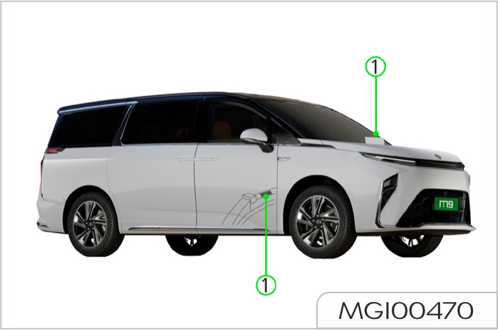
Location of VIN plate
VIN plate (1) is located at front lower side of left B pillar.

The working performance of the high voltage battery pack in the power system of the vehicle is related to ambient temperature, so it is recommended to use the vehicle at the ambient temperature from -15°C to 45°C, to ensure the vehicle in the best working status and extend the life of the high-voltage battery pack. High or low temperature will affect the performance of the high-voltage battery pack and the vehicle.
The working temperature range of the power battery is -30°C to 60°C, and the battery cannot work normally beyond the working temperature range. In the cold weather, it is recommended to store the vehicle in a warm house or park it nearby the charging pile for heating the battery by the connector before use, to avoid affecting traveling.
The driving range depends on the available battery level, vehicle age (current battery life), weather, temperature, road conditions, driving habits, etc. Please note:
At extreme temperature and low battery level, the powerless acceleration and power insufficient may occur due to the battery characteristics. The vehicle driving range may be increased by the following methods:
The standard or dynamic driving range modes may be changed by using the switch on the central control screen, with different values of the driving range, and the latter varies according to your driving habits.
To extend the life of the high voltage battery pack, regularly use the equalization charging method to maintain the high voltage battery pack. It is recommended to use the vehicle at least once every month. It is recommended to slowly charge the vehicle for more than 10 hours every month to extend the life of the high voltage battery pack.
The high voltage battery pack is installed at the position of motorvehicle chassis. It contains many lithium battery cells.
Arbitrary disposal may cause pollution and hazard to the environment. It is prohibited to disassemble and discard without approval. It will be disposed by professional institution. Be sure to dispose of according to the following information or requirements. Details about recycling and disposal of high voltage battery packs can be obtained through consulting Our Service Dealer.
It is recommended that you deliver the waste high voltage battery pack produced due to vehicle scrap or other reasons to our designated recycling services for disposal. Details about maintenance, recycling and disposal of high voltage battery packs can be obtained through consulting Our Service Dealer
The waste high voltage battery pack shall be delivered to other organizations or individuals. If environmental pollution or an safety accident results from the high voltage battery pack removed and disassembled without permission, the owner of the high voltage battery pack shall take the corresponding responsibilities.
High-voltage system on vehicle includes AC and DC high voltage power (can reach over 460V).
High-voltage power is very dangerous and may cause serious injury such as burning, electric shock and even death.
Do not adjust driver seat while the vehicle is moving. Otherwise, the vehicle may lose control and cause an accident.
Manually adjusted driver seat
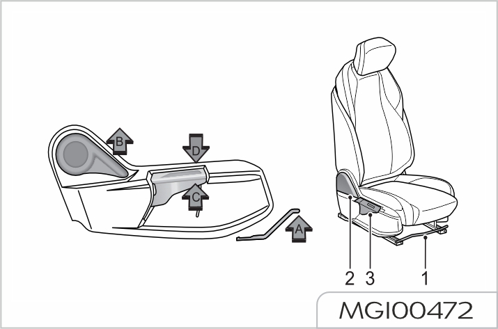
Forward/backward sliding
When the adjuster (1) is pushed up (arrow A), the track will be unlocked, and the seat can be moved forward and backward.
When the seat slides to the desired position, release the adjuster (1) to stop the seat sliding.
Rake adjustment of backrest
Do not recline the seat excessively as the seat belt provides maximum protection only when the angle between the backrest and the upright position is near 25°.
When the angle adjustment armrest (2) is pushed up (arrow B), the backrest is unlocked and can tilt forward and backward. When the seat backrest tilts to the desired position, release the angle adjustment armrest (2) to stop the backrest tilting.
Cushion height adjustment
When the front end of the height adjustment armrest (3) is pushed up (arrow C), the cushion will move upward. When the cushion rises to the desired position, release the height adjustment armrest (3) to stop the cushion movement.
When the front end of the height adjustment armrest (3) is pushed down (arrow D), the cushion will move downward.
When the cushion falls to the desired position, release the height adjustment armrest (3) to stop the cushion movement.
Electrically adjusted driver seat (Type 1)
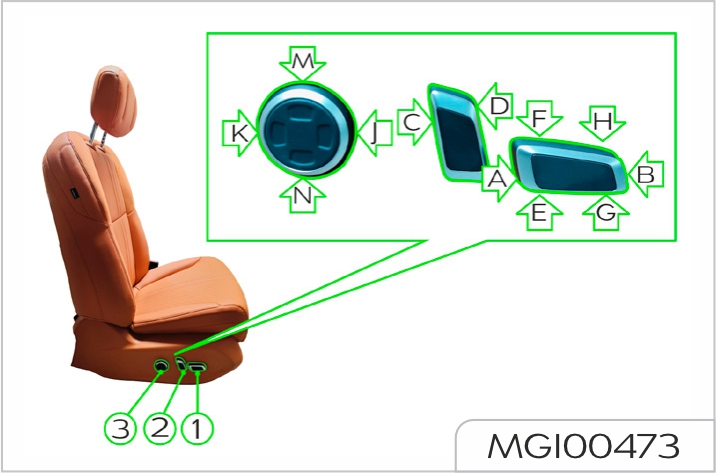
The seat can be freely adjusted regardless of the whether the vehicle is powered on or not. But the electrical adjustment consumes the power of the vehicle battery, which may drain the battery.
Forward/backward sliding
When the button (1) is pushed forward (arrow A), the seat will move forward, and when the seat slides to the desired position, release the button (1) to stop the seat sliding.
When the button (1) is pushed backward (arrow B), the seat will move backward, and when the seat slides to the desired position, release the button (1) to stop the seat sliding.
Rake adjustment of backrest
Do not recline the seat excessively as the seat belt provides maximum protection only when the angle between the backrest and the upright position is near 25°.
When the button (2) is rotated forward (arrow C), the seat backrest will tilt forward, and when the seat backrest tilts to the desired position, release the button (2) to stop the backrest tilting
When the button (2) is rotated backward (arrow D), the seat backrest will tilt backward, and when the seat backrest tilts to the desired position, release the button (2) to stop the backrest tilting.
Cushion height adjustment
When the rear end of the button (1) is pushed up (arrow E), the cushion will move upward, and when the cushion rises to the desired position, release the button (1) to stop the cushion movement.
When the rear end of the button (1) is pushed down (arrow F), the cushion will move downward, and when the cushion falls to the desired position, release the button (1) to stop the cushion movement.
Rake adjustment of cushion
When the front end of the button (1) is pushed up (arrow G), the front end of the cushion will move upward while the upper end of the backrest tilts backward, and when the cushion tilts to the desired position, release the button (1) to stop the cushion movement.
When the front end of the button (1) is pushed down (arrow H), the front end of the cushion will move downward while the upper end of the backrest tilts forward, and when the cushion tilts to the desired position, release the button (1) to stop the cushion movement.
Lumbar support adjustment
When the front end of the button (3) is pressed and held (arrow J), the lumbar support moves forward, and when the lumbar support moves to the desired position, release the button to stop the lumbar support movement.
When the rear end of the button (3) is pressed and held (arrow K), the lumbar support moves backward, and when the lumbar support moves to the desired position, release the button to stop the lumbar support movement.
When the upper end of the button (3) is pressed and held (arrow M), the lumbar support moves upward, and when the lumbar support moves to the desired position, release the button to stop the lumbar support movement.
When the lower end of the button (3) is pressed and held (arrow N), the lumbar support moves downward, and when the lumbar support moves to the desired position, release the button to stop the lumbar support movement.
Armrest adjustment
It applies to vehicles configured with armrest adjustment function.
The armrest can be adjusted upwards from the lowest position as needed. There are 3 positions in total.
When it is required to lower the armrest from a higher position, it is necessary to raise the armrest to the highest position first, then lower the armrest to the lowest position, and then adjust the armrest upwards to the desired position.
Electrically adjusted driver seat (Type 2)
Regardless of whether the vehicle is powered on or not, the forward/ backward sliding, rake adjustment of backrest, rake adjustment of cushion, cushion height adjustment. seat lumbar support adjustment and memory position function can be realized for the seat, but the electrical adjustment consumes the power of the vehicle battery, which may drain the battery. The massage function can be used only after the vehicle is powered on.
You can enter the seat interface on the center console screen to perform function adjustment for the corresponding seat.
Forward/backward sliding
When the button (1) is pushed forward (arrow A), the seat will move forward, and when the seat slides to the desired position, release the button (1) to stop the seat sliding.
When the button (1) is pushed backward (arrow B), the seat will move backward, and when the seat slides to the desired position, release the button (1) to stop the seat sliding.
Rake adjustment of backrest
Do not recline the driver seat excessively, as the seat belt provides maximum protection only when the angle between the backrest and the upright position is near 25°.
When the button (2) is rotated forward (arrow C), the seat backrest will tilt forward, when the seat backrest tilts to the desired position, release the button (2) to stop the backrest tilting.
When the button (2) is rotated backward (arrow D), the seat backrest will tilt backward, and when the seat backrest tilts to the desired position, release the button (2) to stop the backrest tilting.
Cushion height adjustment
When the rear end of the button (1) is pushed up (arrow E), the cushion will move upward, and when the cushion rises to the desired position, release the button (1) to stop the cushion movement.
When the rear end of the button (1) is pushed down (arrow F), the cushion will move downward, and when the cushion falls to the desired position, release the button (1) to stop the cushion movement.
Rake adjustment of cushion
When the front end of the button (1) is pushed up (arrow G), the front end of the cushion will move upward while the upper end of the backrest tilts backward, and when the cushion tilts to the desired position, release the button (1) to stop the cushion movement.
When the front end of the button (1) is pushed down (arrow H), the front end of the cushion will move downward while the upper end of the backrest tilts forward, and when the cushion tilts to the desired position, release the button (1) to stop the cushion movement.
Lumbar support adjustment
When the front end of the button (3) is pressed and held (arrow J), the lumbar support moves forward, and when the lumbar support moves to the desired position, release the button to stop the lumbar support movement.
When the rear end of the button (3) is pressed and held (arrow K), the lumbar support moves backward, and when the lumbar support moves to the desired position, release the button to stop the lumbar support movement.
When the upper end of the button (3) is pressed and held (arrow M), the lumbar support moves upward, and when the lumbar support moves to the desired position, release the button to stop the lumbar support movement.
When the lower end of the button (3) is pressed and held (arrow N), the lumbar support moves downward, and when the lumbar support moves to the desired position, release the button to stop the lumbar support movement.
Memory position function
The seat memory position function has 3 positions. After entering the seat interface on the center console screen, adjust the seat (backrest/ forward/backward sliding/front height adjustment/rear lifting and other functions) to the desired position first, select the driver memory touch button 1/2/3, and press and hold it for about 2 seconds, until the center console screen prompts successful saving (If we adjust the seat to a position other than memory 1, and want to restore to the position of memory 1, short press the memory button 1, the seat will move to the stored position of memory 1).
To adjust the electrically adjusted front occupant seat (type 2), select the front occupant memory touch button, with the same operation method as the driver memory
Massage function
The seat massage function has 8 modes, and each mode has three positions: high, medium and low. Enter the seat interface on the center console screen, select the driver massage touch button, and adjust according to the prompts.
To adjust the electrically adjusted front occupant seat (type 2), select the front occupant massage touch button and adjust according to the prompts.
Heating function
The seat heating function has 3 positions. Enter the A/C interface on the center console screen, select the driver seat heating touch button, and adjust according to the prompts.
To adjust the electrically adjusted front occupant seat (type 2), select the front occupant seat heating touch button and adjust according to the prompts.
Ventilation function
The seat ventilation (blowing) function has 3 positions. Enter the A/C interface on the center console screen, select the driver seat ventilation touch button, and adjust according to the prompts.
To adjust the electrically adjusted front occupant seat (type 2), select the front occupant seat ventilation touch button and adjust according to the prompts.
The cushion heating function and ventilation function cannot be used at the same time.
Manually adjusted front occupant seat
Forward/backward sliding
Pull up the adjuster (1), and slide the seat to the desired position.
Release the adjuster (1) and check that the seat is locked in position.
Rake adjustment of backrest
Do not recline the front occupant seat excessively, as the seat belt provides maximum protection only when the angle between the backrest and the upright position is near 25°.
Slightly recline forward and pull up the adjuster (2); the seat backrest rebounds automatically. Then lean against the backrest to adjust it to the desired angle. Release the adjuster (2) and check that the seat backrest is locked in position.
Armrest adjustment
The armrest can be adjusted upwards from the lowest position as needed. There are 3 positions in total.
When it is required to lower the armrest from a higher position, it is necessary to raise the armrest to the highest position first, then lower the armrest to the lowest position, and then adjust the armrest upwards to the desired position.
Electrically adjusted front occupant seat (Type 1)
Only forward/backward sliding, rake adjustment of backrest and lumbar support adjustment can be made, and its adjustment method is the same as that of electrically adjusted driver seat (type 1).
Electrically adjusted front occupant seat (Type 2)
Only forward/backward sliding, rake adjustment of backrest, memory position function, lumbar support adjustment, massage function, heating function and ventilation function can be realized, and its adjustment method is the same as that of the electrically adjusted driver seat (type 2).
Manually adjusted single seat

The adjuster of the right seat is on the right of the seat, while the adjuster of the left seat is on the left of the seat.
Forward/backward sliding
Lift the adjuster (1) upward, and adjust the seat position forward and backward by pulling/pushing it forward/backward with both feet. Release the adjuster (1), and check that the seat is locked in position.
Rake adjustment of backrest
Pull up the adjuster (2), and then lean against the backrest to adjust it to the desired angle. Release the adjuster (2) and check that the seat backrest is locked in position.
Seat cup holder
The retractable cup holder automatically pops out by tapping slightly; to retract the cup holder, push it in until it locks.
The retractable cup holder of the left single seat is on the right of the seat.
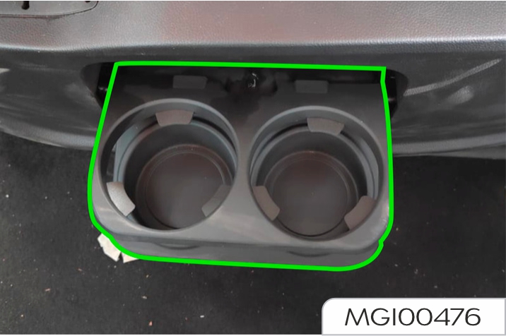
The right single seat has no cup holder, but has two USB charging ports.
Armrest adjustment
The armrest can be adjusted upwards from the lowest position as needed. There are 8 positions in total.
When it is required to lower the armrest from a higher position, it is necessary to raise the armrest to the highest position first, then lower the armrest to the lowest position, and then adjust the armrest upwards to the desired position.
Electrically adjusted single seat (Type 1)
The seat can be freely adjusted regardless of whether the vehicle is powered on or not. But the electrical adjustment consumes the power of the vehicle battery, which may drain the battery
The adjustment button of the right seat is on the right of the seat, while the adjustment button of the left seat is on the left of the seat.
Forward/backward sliding
When the button (1) is pushed forward (arrow A), the seat will move forward, and when the seat slides to the desired position, release the button (1) to stop the seat sliding.
When the button (1) is pushed backward (arrow B), the seat ill move backward, and when the seat slides to the desired position, release the button (1) to stop the seat sliding.
Rake adjustment of backrest
Do not recline the seat excessively as the seat belt provides maximum protection only when the angle between the backrest and the upright position is near 25°.
When the button (2) is rotated forward (arrow C), the seat backrest will tilt forward, and when the seat backrest tilts to the desired position, release the button (2) to stop the backrest tilting.
When the button (2) is rotated backward (arrow D), the seat backrest will tilt backward, and when the seat backrest tilts to the desired position, release the button (2) to stop the backrest tilting.
Seat leg support adjustment
When the button (1) is pushed forward (arrow E), the leg support will tilt upward, and when the leg support tilts to the desired position, release the button (1) to stop the leg support tilting.
When the rear end of the button (1) is pushed down (arrow F), the cushion will move downward, and when the cushion falls to the desired position, release the button (1) to stop the cushion movement.
Lumbar support adjustment
When the front end of the button (3) is pressed and held (arrow J), the lumbar support moves forward, and when the lumbar support moves to the desired position, release the button to stop the lumbar support movement.
When the rear end of the button (3) is pressed and held (arrow K), the lumbar support moves backward, and when the lumbar support moves to the desired position, release the button to stop the lumbar support movement.
When the upper end of the button (3) is pressed and held (arrow M), the lumbar support moves upward, and when the lumbar support moves to the desired position, release the button to stop the lumbar support movement.
When the lower end of the button (3) is pressed and held (arrow N), the lumbar support moves downward, and when the lumbar support moves to the desired position, release the button to stop the lumbar support movement.
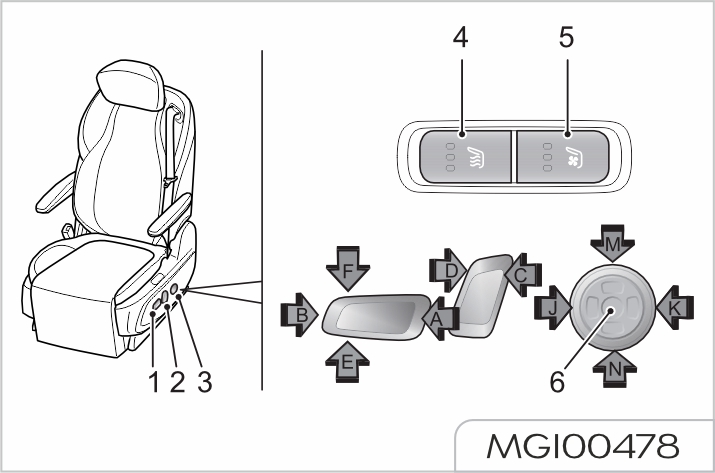
Massage function
When (6) in the middle of the button (3) is pressed and held, the massage starts, first up and then down, and then massage at the same time, in cycle and without time limit.
Press (6) in the middle of the button (3) again or activate the lumbar support in the midway to stop massage.
Ventilation function
When pressing the ventilation button (5) once, the fan starts in the 3rd position, and LED1, LED2, and LED3 are on; when pressing the ventilation button (5) twice, the fan starts in the 2nd position, LED1 is off, while LED2 and LED3 are on; when pressing the ventilation button (5) three times, the fan starts in the 1st position, LED1 and LED2 are off, while LED3 is on. When pressing the ventilation button again, the ventilation function is deactivated, and LED1, LED2, and LED3 are off.
Heating function
When pressing the heating button (4) once, the heater starts in the 3rd position, and LED4, LED5, and LED6 are on; when pressing the heating button (4) twice, the heater starts in the 2nd position, LED4 is off, while LED5 and LED6 are on; when pressing the heating button (4) three times, the heater starts in the 1st position, LED4 and LED5 are off, while LED6 is on.
When pressing the heating button again, the heating function is deactivated, and LED4, LED5, and LED6 are off.
The cushion heating function and ventilation function cannot be used at the same time.
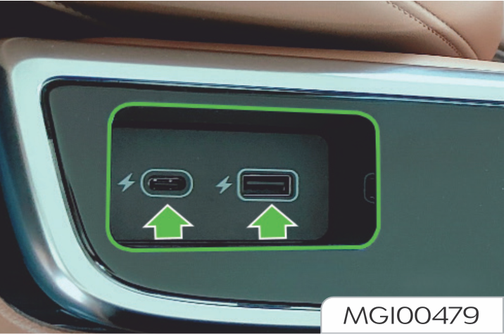
Seat cup holder
The retractable cup holder automatically pops out by tapping slightly; to retract the cup holder, push it in until it locks.
The retractable cup holder of the left single seat is on the right of the seat.
The right single seat has no cup holder, but has USB and Type-C charging ports.
Armrest adjustment
The armrest can be adjusted upwards from the lowest position as needed. There are 8 positions in total.
When it is required to lower the armrest from a higher position, it is necessary to raise the armrest to the highest position first, then lower the armrest to the lowest position, and then adjust the armrest upwards to the desired position.
Electrically adjusted single seat (Type 2)
The seat can be freely adjusted regardless of whether the vehicle is powered on or not. But the electrical adjustment consumes the power of the vehicle battery, which may drain the battery.
You can enter the seat interface on the center console screen to perform function adjustment for the corresponding seat.
Forward/backward sliding
It is controlled via the armrest screen (3). Select the Basic Function button in the seat homepage interface, long press the F symbol to slide the seat forward, and long press the B symbol to slide the seat backward.
Rake adjustment of backrest
It is controlled via the armrest screen (3). Select the Basic Function button in the seat homepage interface, long press the Tilt Froward symbol to tilt the seat forward, and long press the Tilt Backward symbol to tilt the seat backward.

Seat leg support and lumbar support adjustment
It is controlled via the armrest screen (3). Select the Leg and Lumbar Support button in the seat homepage interface, long press the Raise symbol at the leg support to raise the seat leg support, and long press the Lower symbol at the leg support to lower the seat leg support. Long press the Extend symbol at the leg support to extend the seat leg support, and long press the Retract symbol at the leg support to retract the seat leg support. Select the Leg and Lumbar Support button in the seat homepage interface, and long press the symbols at the lumbar support to adjust the seat lumbar support forward/ backward/upward/downward.
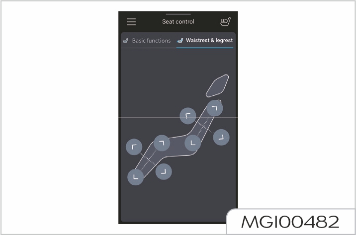
Headrest adjustment
It is controlled via the armrest screen (3). Select the Basic Function button in the seat homepage interface, long press the Raise symbol to raise the seat headrest continuously, and long press the Lower symbol to lower the seat headrest continuously.
Short press the Raise symbol to raise it for a short distance, and short press the Lower symbol to lower it for a short distance.
Lateral sliding
It is controlled via the armrest screen (3). Select the Basic Function button from the seat homepage options, and long press the L/R symbol to slide the seat to left/right.
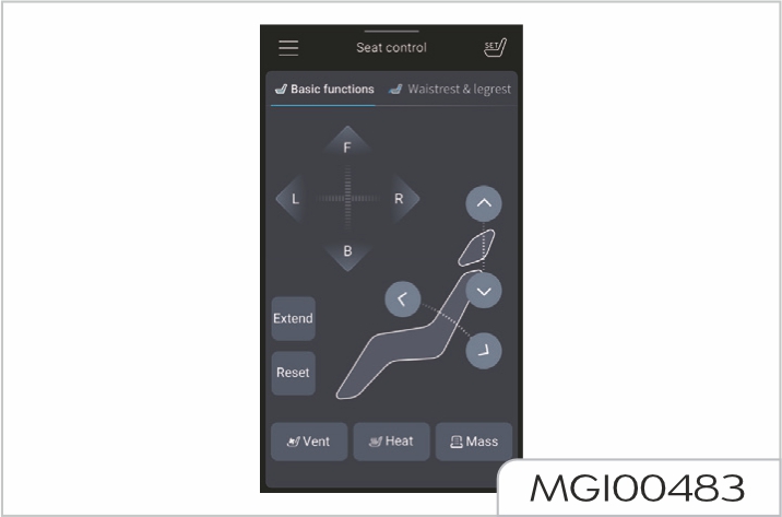
Ventilation
It is controlled via the armrest screen (3). Select the Basic Function button in the seat homepage interface, and then select the Ventilation button to enter the ventilation interface.
Ventilation has 3 positions, which is OFF by default. Select the desired position to recall it.
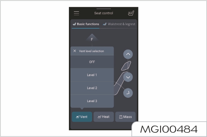
You can also adjust it by entering the A/C interface on the center console screen. The seat ventilation (blowing) function has 3 positions. Enter the A/C interface, select the left/right ventilation touch button, and adjust the ventilation function of the 2nd row left/right seat according to the prompts.
The cushion heating function and ventilation function cannot be used at the same time.
Heating
It is controlled via the armrest screen (3). Select the Basic Function button in the seat homepage interface, and then select the Heating button to enter the heating interface. Heating has 3 positions, which is OFF by default. Select the desired position to recall it.

You can also adjust it by entering the A/C interface on the center console screen. The seat heating function has 3 positions. Enter the A/C interface, select the left/right heating touch button, and adjust the heating function of the 2nd row left/right seat according to the prompts.
The cushion heating function and ventilation function cannot be used at the same time.
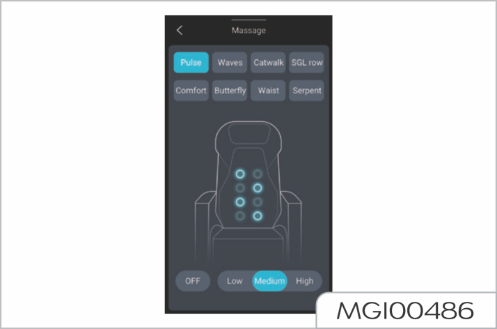
Massage
It is controlled via the armrest screen (3). Select the Basic Function button in the seat homepage interface, and then select the Massage button to enter the massage interface. Massage has 8 modes, each with 3 positions. Select "OFF" to deactivate the massage function.
Position memory
It is controlled via the armrest screen (3). Select the button from the seat homepage options. After opening, three positions can be selected. Select a position, long press it to save this position, and short press it to adjust the seat from other positions to this memory position.
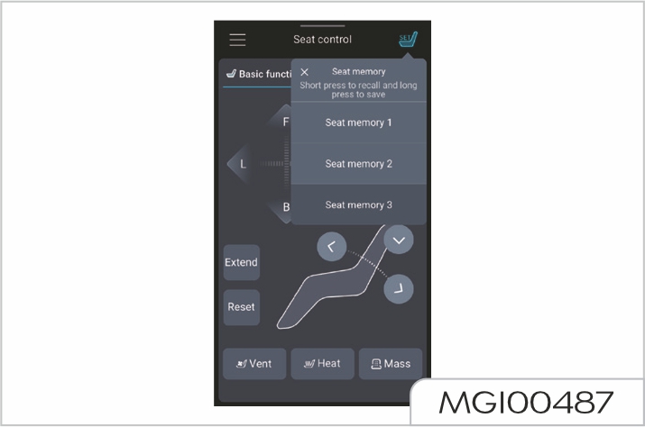
One-touch reclining/retracting
It is controlled via the armrest screen (3). Select the Basic Function button in the seat homepage interface, and then select the Extend button to recline the seat flat. The seat in the armrest screen is reclined to the calibrated position. Select the Reset button to retract the seat to the calibrated position.

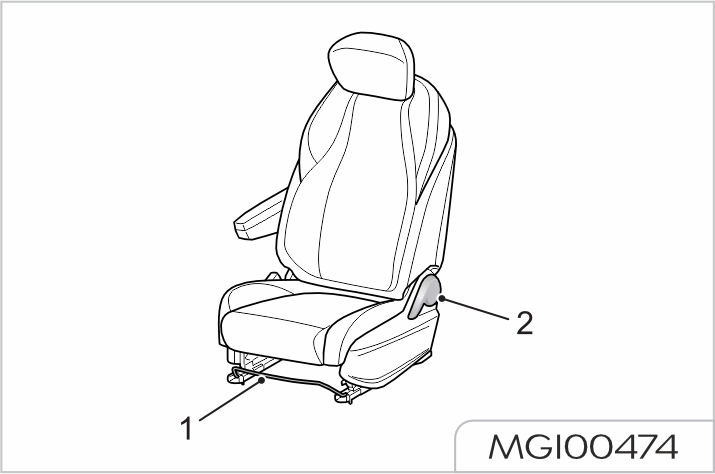
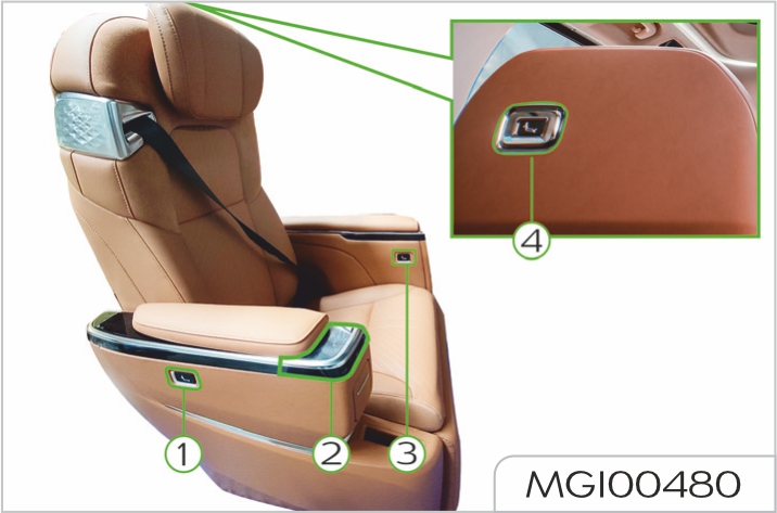
One-touch reset function
The button (1) on the side of the seat is for entry. Long press the button (1) to move the front occupant seat, 2nd row seats and 3rd row seats (the 3rd row seats of vehicles with 7 seats do not move) to the calibrated entry position.
The button (2) on the inner side of the seat is the reset button.
Long press the button (2) to return the seat to the calibrated position.
The button (4) at the rear end of the seat backrest is for exit.
Long press the button (4) to move the front occupant seat, 2nd row seats and 3rd row seats (the 3rd row seats of vehicles with 7 seats do not move) to the calibrated entry position.
The buttons (1), (2) and (4) have the function to pause seat movement, i.e. during the seat movement or when the seat moves and the armrest screen control fails, short press any of the buttons (1), ( 2) and (4) to pause the seat movement.
Cover above armrest screen
The cover above the armrest screen can be slided forward or backward by pressing the following buttons.
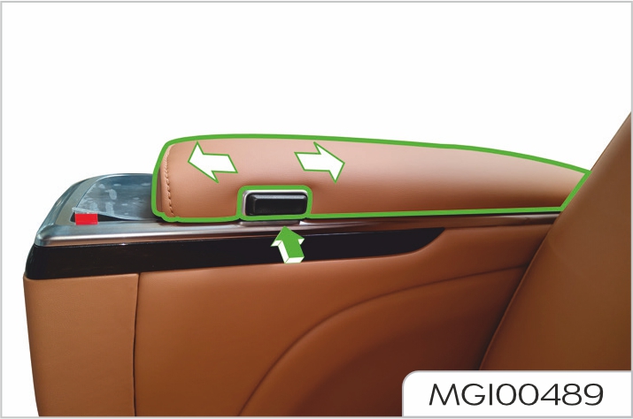
Table function
Open the cover on the inner large armrest and press the following button. After pressing the button, the table will pop out of the armrest, and then it can be laid flat or rolled out. The table can be unfolded and slided forward.
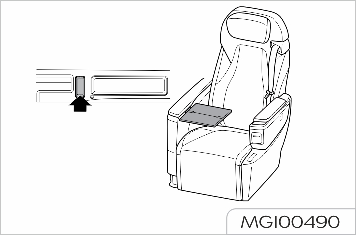
To put back the table, fold it first, move it to the last position to make it upright, push it down into the large armrest until a "click" sound is heard, indicating that it has been completely put back, and then close the cover on the inner large armrest.
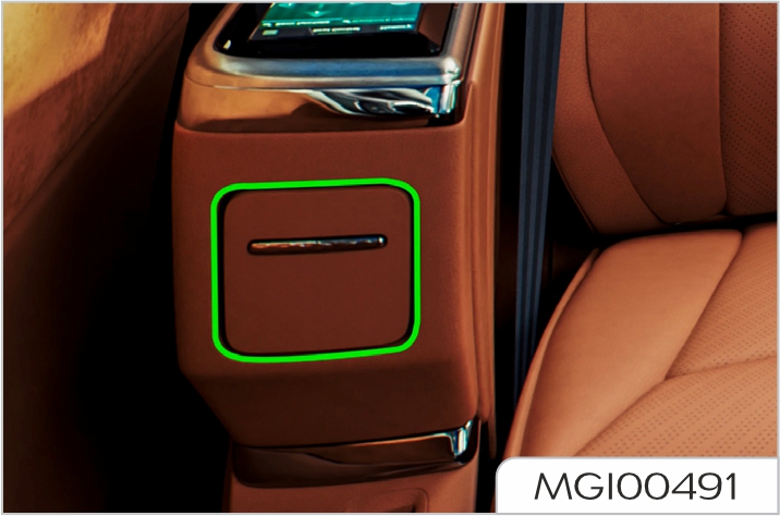
Seat cup holder
The pop-up cup holder automatically pops out by pressing it inward; to retract the cup holder, push it in until it locks. The pop-up cup holder of the left single seat is on the left of the seat.
The pop-up cup holder of the right single seat is on the right of the seat.
Single fixed seat in manually adjusted triple seat
The adjuster of right single seat is on the right of the seat, the adjuster of left single seat is on the left of the seat, and the adjuster of middle single seat is on the right of the seat.
Rake adjustment of backrest
Pull up the adjuster (1) or pull the adjuster strap (2) to adjust it to the desired angle. Release the adjuster (1) or adjuster strap (2) and check that the backrest is locked in position. The seat backrest can be tilted forward or laid flat.
Manually adjusted triple seat
Type-1

Type-2
Forward/backward sliding
Lift the adjuster (1)/(4) upward, and adjust the seat position forward and backward by pulling/pushing it forward/backward with both feet. Release the adjuster (1) or adjuster (4), and check that the seat is locked in position. The forward and backward adjuster for the triple seat is located under the seat.
Rake adjustment of backrest
Slightly recline forward and pull up the adjuster (2)/(3); the seat backrest rebounds automatically. Then lean against the backrest to adjust it to the desired angle. Release the adjuster (2)/(3) and check that the seat backrest is locked in position.
When the backrest is laid flat, it can be unlocked by pulling the adjuster (5)/(6) to adjust it to the desired position.
The rake adjusters for the triple seat are located on the left and right of the seat.
Electrically adjusted single seat
The seat can be freely adjusted regardless of whether the vehicle is powered on or not. But the electrical adjustment consumes the power of the vehicle battery, which may drain the battery.
The adjustment button of the right seat is on the left of the seat, while the adjustment button of the left seat is on the right of the seat.
You can enter the seat interface on the center console screen to perform function adjustment for the corresponding seat.
Forward/backward sliding
When the button (1) is pushed forward (arrow A), the seat will move forward, and when the seat slides to the desired position, release the button (1) to stop the seat sliding.
When the button (1) is pushed backward (arrow B), the seat will move backward, and when the seat slides to the desired position, release the button (1) to stop the seat sliding.
Rake adjustment of backrest
Do not recline the seat excessively as the seat belt provides maximum protection only when the angle between the backrest and the upright position is near 25°.
When the button (2) is rotated forward (arrow C), the seat backrest will tilt forward, and when the seat backrest tilts to the desired position, release the button (2) to stop the backrest tilting.
When the button (2) is rotated backward (arrow D), the seat backrest will tilt backward, and when the seat backrest tilts to the desired position, release the button (2) to stop the backrest tilting.
Seat leg support adjustment
When the button (1) is pushed forward (arrow E), the leg support will tilt upward, and when the leg support tilts to the desired position, release the button (1) to stop the leg support tilting.
When the rear end of the button (1) is pushed down (arrow F), the cushion will move downward, and when the cushion falls to the desired position, release the button (1) to stop the cushion movement.
Lumbar support adjustment
When the front end of the button (3) is pressed and held (arrow J), two air bags of lumbar support deflate and the lumbar support lowers; release the button to stop lowering the lumbar support.
When the rear end of the button (3) is pressed and held (arrow K), two air bags of lumbar support inflate and the lumbar support rises; release the button to stop raising the lumbar support.
When the upper end of the button (3) is pressed and held (arrow M), the upper air bag of lumbar support inflates/the lower air bag deflates, the upper end of lumbar support rises, and the lower end lowers; release the button to stop.
When the lower end of the button (3) is pressed and held (arrow N), the upper air bag of lumbar support deflates/the lower air bag inflates, the upper end of lumbar support lowers, and the lower end rises; release the button to stop.
Massage function
When (6) in the middle of the button (3) is pressed and held, the massage starts, first up and then down, and then massage at the same time, in cycle and without time limit.
Press (6) in the middle of the button (3) again or activate the lumbar support in the midway to stop massage.
Heating function
When pressing the heating button (4) once, the heater starts in the 3rd position, and LED4, LED5, and LED6 are on; when pressing the heating button (4) twice, the heater starts in the 2nd position, LED4 is off, while LED5 and LED6 are on; when pressing the heating button (4) three times, the heater starts in the 1st position, LED4 and LED5 are off, while LED6 is on.
When pressing the heating button again, the heating function is deactivated, and LED4, LED5, and LED6 are off.
The cushion heating function and ventilation function cannot be used at the same time.
Ventilation function
When pressing the ventilation button (5) once, the fan starts in the 3rd position, and LED1, LED2, and LED3 are on; when pressing the ventilation button (5) twice, the fan starts in the 2nd position, LED1 is off, while LED2 and LED3 are on; when pressing the ventilation button (5) three times, the fan starts in the 1st position, LED1 and LED2 are off, while LED3 is on. When pressing the ventilation button again, the ventilation function is deactivated, and LED1, LED2, and LED3 are off.
The cushion heating function and ventilation function cannot be used at the same time.
The 3rd row electrically adjusted single seats can also be slided forward and backward through the rear body side buttons.
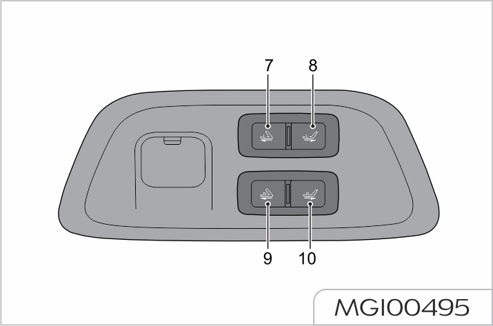
When long pressing the button (7), the left single seat moves forward (retract the leg support first when it is open), and the backrest is retracted to the calibrated angle.
When long pressing the button (8), the left single seat backrest returns to the calibrated angle first, and then the seat moves backward.
When long pressing the button (9), the right single seat moves forward (retract the leg support first when it is open), and the backrest is retracted to the calibrated angle.
When long pressing the button (10), the right single seat backrest returns to the calibrated angle first, and then the seat moves backward.
During the above operations, release the button to stop the seat movement.
Armrest adjustment
The armrest can be adjusted upwards from the lowest positionas needed. There are 8 positions in total.
When it is required to lower the armrest from a higher position, it is necessary to raise the armrest to the highest position first, then lower the armrest to the lowest position, and then adjust the armrest upwards to the desired position.
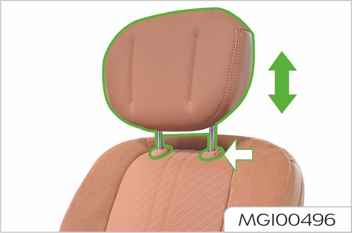
To reduce the risk of neck or head injury, the headrest should be adjusted to support the back of the head but not the neck. Do not adjust the headrest while the vehicle is in motion.
Two-way adjustable headrest
Press the arrowed button to push down or pull up the headrest to adjust the headrest to the desired position. When pulling to a proper position, the headrest can be pulled out.
The seat and its occupant restraint system have been designed to reduce personal injury to a minimum in the event of an accident. For optimum effectiveness, the following points should be observed.
Improperly wearing or using seat belts may cause serious personal injury or death. Seat belts are life saving equipment. In a collision, unrestrained occupants may collide anywhere inside the vehicle or be possibly thrown out, resulting in injury to themselves or to other occupants. When riding in a vehicle, the driver and any adult (or any adult sized child) must always wear the seat belt.
Do NOT slacken the webbing by pulling the belt away from your body. To be fully effective, the webbing must remain tightly around your body at all times.
Avoid wearing thick, bulky clothing. Put the shoulder belt of seat belt across the center of the shoulder and the lap belt close to the body to go over the hips. Strictly prohibit the use of slack and twisted seat belts, and seat belts can not be twisted to wear
Never use a seat belt for more than one adult, and never use it to secure an additional object or a child.
Each seat belt can only be used by one occupant. It's dangerous to wrap a seat belt around a child in the occupant arms.
When wearing a seat belt, ensure that it is not twisted or slack. Otherwise the smooth operation of the belt may be impeded. The buckle release button must face outwards.
Do not allow a baby or infant to be carried on the lap. The force of a crash can increase effective body weight, making it impossible to hold onto the child.
Do not allow foreign matters (particularly sugary food and drinks) to enter the seat belt bucklesuch substances may render the buckle inoperative.
If the seat belt has been used in a serious accident, or is seriously worn, or has been cut, or the visual load meter shows that the seat belt is no longer available, or the seat belt is a pretensioning seat belt with the pretensioner triggered, the seat belt assembly must be replaced.
Pregnant women should ask their doctor for advice about the safest way to wear seat belts.
A seat belt must not be altered or modified in any way, since such changes may render the belt ineffective.
Do not attempt to dismantle, repair or lubricate the retractor or buckle mechanisms.
Each seat belt is fitted with a retractor. When the seat belt is pulled out slowly, the retractor can ensure that the seat belt is retracted freely. But if the seat belt is pulled out too fast or under a sudden impact (a sudden deceleration, acceleration, sharp turn), the seat belt will be locked. See "Seat belts" in Maintenance and Service section for the specific inspection methods.
When the seat belt is not used, be sure to retract the seat belt webbing completely, straighten the webbing and put the tongue in place, and keep the webbing and tongue clean to prevent dust and impurities.
Be careful to avoid the erosion of webbing by polishing agents, oils and chemicals (especially battery acid). It can be cleaned safely with mild soap and water. After wear, erosion or damage of the webbing occurs, the seat belt assembly should be replaced.
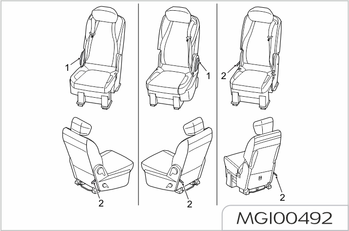
The driver seats and front occupant seats of the vehicles of this series can be configured with adjustable nonpretensioning force-limiting seat belts and adjustable dual pretensioning force-limiting seat belts; the 2nd row occupant seats may be configured with non-pretensioning non-forcelimiting seat belts and pretensioning force-limiting seat belts; the 3rd row seats may be configured with threepoint belts.
Insert the tongue into the buckle until a distinct click is heard, which indicates the belt is locked.
Seat belt with pretensioner (shoulder belt pretensioner)
In the event of serious collision accident, the pretensioner (integrated into the retractor) will be activated by the sensor, the shoulder belt (1) will be contracted a little immediately to prevent the occupants from moving forward and make them seated securely, so that it improves the function of the seat belt further.
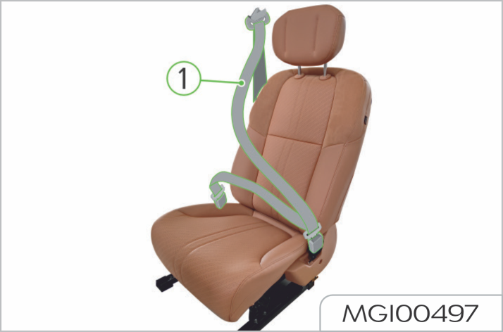
Seat belt with dual pretensioners (shoulder/hip belt pretensioner)
In the event of serious collision accident, the dual pretensioners (one integrated into the retractor, the other integrated into the side lap strap pretensioner) will be activated by the sensor, the shoulder belt (1) and the lap strap (2) will be contracted a little immediately at the same time to prevent the occupants from moving forward and make them seated securely, so that it improves the function of the seat belt further.
The outer locking tab (3) does not need to be unlocked in the daily use. The outer locking tab (3) should be unlocked by using the special tool, please ask Our Service Dealer to unlock it, if necessary.

Front seat belt
Fastening
The seat belt is pulled out slowly, passes through the shoulder to be fastened in front of the body, verify that the belt is not twisted or tied, then push the tongue into the buckle until a click is heard.
Loosening
Press the red button on the buckle, then the tongue will pop out under the action of the elastic force. Push the tongue back manually, so that the automatic seat belt retractor can contract the whole seat belt more easily.

2nd row seat belts
The fastening and loosening methods for the 2nd row single seat belts are the same as that for front seat belts.
3rd row seat belts
The fastening and loosening methods for the 3rd row single seat belts are the same as that for front seat belts.
The fastening and loosening methods for the 3rd row dual seat belts are the same as that for front seat belts.
The fastening and loosening methods for the seat belts on both sides of the 3rd row triple seat are the same as that for front seat belts.
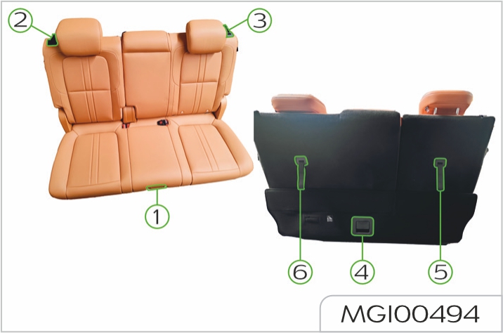
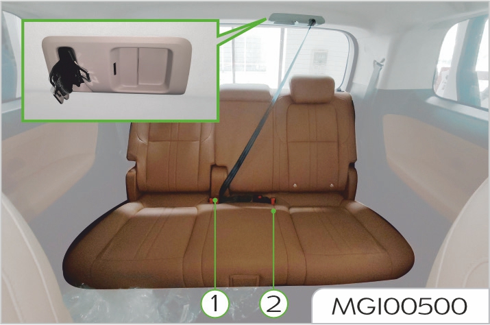
The middle seat of the 3rd row triple seat uses a roof-mounted seat belt, which is fastened and loosened as follows.
Fastening
Pull the seat belt out of the roof, push the fixed tab (2) into the left buckle, then the movable tab (1) is passed through the abdomen and pushed into the right buckle.
Loosening
To remove the seat belt comfort guide, squeeze both sides of the seat belt together, and remove the seat belt from the guide. Then, put the guide in the seat backrest pocket.
The movable tab (1) is unlocked by pressing the red button on the right buckle.
The fixed tab (2) is pulled out by pressing the red button on the left buckle. Push the tongue back manually, so that the automatic seat belt retractor can contract the whole seat belt more easily.
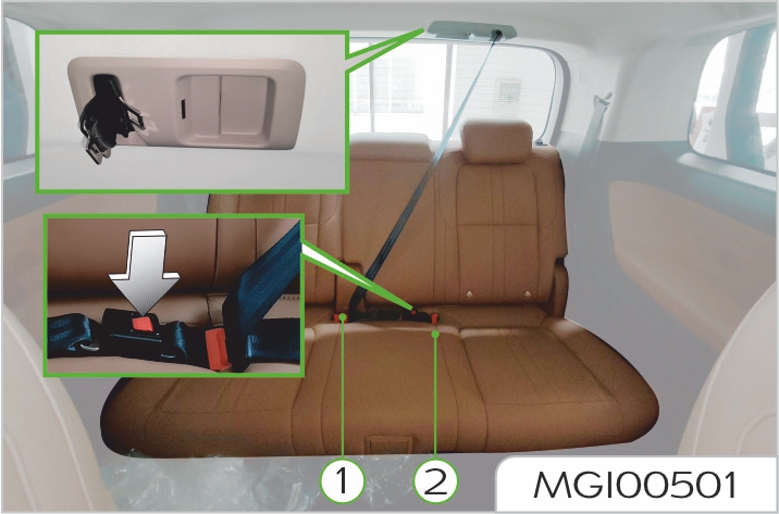
When the seat belt is retracted into the roof, the tongue can be clamped onto the roof
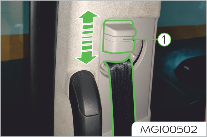
Seat belt height adjustment
Ensure that the slide adjuster is secure after making an adjustment.
Do not adjust the height of the driver seat belt while driving, as the control of vehicle may be lost.
Only the height of the driver seat and front occupant seat belts can be adjusted.
Press the button (1) up and slide the height adjuster on the top of seat belt up and down to suit the height of the occupant. Release the button (1) at the proper position, and pull the seat belt forcibly to ensure that the height adjuster is locked reliably.
Seat belt warning light
See "Warning lights and indicators" in this section for the specific description of the "Seat belt warning light".
Do not damage or repair a pretensioner. It contains an ignition device, so that any maintenance can only be carried out by Our Service Dealer.
Pretensioners will not function after activation and must be replaced. In the event of a collision, ensure that the pretensioner and all seat belt components have been maintained by Our Service Dealer.
The seat belt pretensioner works together with the airbag to reduce the risk of injury in the event of a head-on collision.
No safety system can provide complete protection for personal injury or death in a severe crash. Injuries or death can occur, even if seat belts are worn properly and the airbags are inflated.
After inflation some airbag components are hot - Do NOT touch until they have cooled. An airbag is inflated with considerable force and can cause facial abrasions and other injuries. These effects can be minimized by ensuring that you and your occupant(s) are wearing seat belts. The driver seat should be adjusted to be as far rearwards as possible while maintaining the proper control of the vehicle. Always hold the steering wheel by its rim, so that the airbag can be inflated without obstruction.
Always hold the steering wheel by its rim, so that the airbag can be inflated without obstruction.
Never attach accessory items e.g. a mobile phone bracket, cup holder, cassette tray, etc. to the steering wheel cover or the airbag module cover of the dashboard, or stick/insert anything to an airbag module cover. Otherwise, these objects could interfere with inflation of the airbag, or after the airbag is inflated, they will be propelled into the vehicle to cause injury to occupants.
Do not allow an occupant to obstruct the deployment of the airbag by putting feet, knees, etc. in contact with, or in close proximity to the airbag module cover of the dashboard.
It is forbidden to put the seat cover and other related decorative seat items that affect the deployment of seat airbags on the seats equipped with seat airbags.
Do not modify the seats equipped with seat airbags at will.
Do not paste any sharp objects on A, B, C and D pillars of the vehicle at will, and modify A, B, C and D pillars, so as to avoid injuries to occupants during the operation of airbags.
The seat belt pretensioner works together with the airbag to reduce the risk of injury in the event of a head-on collision.
Do not attempt to remove or pierce the steering wheel, or hit it violently.
Do not allow another person, animal or object to occupy the space between the driver and the deploying range of the airbag. The same applies on the occupant side if an airbag is fitted.
Do not attempt to maintain the steering wheel, steering column, any airbag system or pretensioner component, or the airbag components with wiring around. Otherwise, it could cause inadvertent activation of the system resulting in personal injury.
Do not modify the front of the vehicle in any way as this could adversely affect airbag deployment. If the vehicle is to be scrapped, undeployed airbags are potentially dangerous and should be deployed before scrapping. This operation must be done by professional staff.
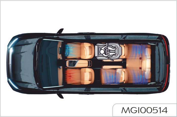
This vehicle can be equipped with the driver airbag, front occupant airbag, driver side airbag, front occupant side airbag, driver seat far-end side airbag and side air curtain.
Both the airbag and the pretensioner are supplementary protection device, while the seat belt is still the main protection device and must be worn during driving.
Airbag and pretensioner check
After the vehicle is powered on, if the warning light is not turned on or not turned off after about 6 seconds, or turned on when driving, it indicates that the seat belt pretensioner or the airbag is faulty. Contact Our Service Dealer for service as soon as possible.
Each time the vehicle is powered on,
the "airbag warning
light (red)"![]() will illuminate for about 6 seconds,
which indicates that the airbag and
seat belt pretensioner inspection is
in progress; it goes off after about
6 seconds, which indicates that the
airbag and seat belt pretensioner are
normal.
will illuminate for about 6 seconds,
which indicates that the airbag and
seat belt pretensioner inspection is
in progress; it goes off after about
6 seconds, which indicates that the
airbag and seat belt pretensioner are
normal.
Airbag deployment
Incorrect sitting posture or sitting or resting on the place close to the airbag will result in serious and even fatal injuries when the airbag is deployed.
In order to reduce the injuries caused during the airbag deployment, the seat belt must be always worn properly. The driver and front occupant must have a good sitting posture, and adjust their seat positions to enable them to be far enough away from the front airbag, so as to avoid causing serious injury or death when the airbag is deployed. For vehicles equipped with side airbags and side air curtains, it is also important to ensure that upper extremities are far enough away from the side of the vehicle, avoiding injuries due to airbag deployment.
When the airbag is deployed, children not properly protected may suffer serious injury and even death.
Do not hold a child in your arms or put the child on your lap when riding on a vehicle.
Do not allow children to ride on a vehicle without protection, and it is prohibited to stick any part of the body out of the window
The airbag deployment may cause body surface abrasion or bruise or burns due to explosion.
There must be no obstacle in the airbag inflation channel. It is prohibited to place any object between the occupant and the airbag. It is prohibited to fix or place any object on the steering wheel cover or the frontal airbag cover of instrument cluster and its vicinity. It is prohibited to place accessories around the airbag system. If there is obstacle between the occupant and the airbag, the airbag may not be properly inflated, or squeeze the obstacle into the body of occupant, causing serious injury or death.
Do not knock on or crash the airbag or positions of relevant components, to avoid causing serious injury or death due to airbag deployment.
When it is deployed, some airbag components are hot, so do not contact it before cooling down.
In case of crash, airbag control module detects speed change caused by crash to determine airbag deployment. The airbag will deploy instantaneously and powerfully with a loud noise. When the vehicle is subject to serious front crash, fully deployed airbag along with properly worn seat belt can limit the movement of the driver and the front occupant, thereby reducing the risk of injury to the head and chest. For vehicles equipped with side airbags and side air curtains, if the side of vehicle is seriously crashed, fully deployed side airbag will form an air cushion between the occupant and the side of vehicle, thereby reducing the risk of injury to the side of occupant body
When you are sitting upright in the seat and leaning against the seat backrest, the seat belt and the airbag can provide the most effective protection. In case of a serious crash, the airbag deploys violently. At this moment, if you or other occupant does not properly use the seat belt, and tilts the body forward, reclines or has other incorrect posture, the possibility of serious injury or death in an accident will be high.

Frontal airbag
Do not install the children restraints on the front occupant seat. Frontal airbag deployment will cause serious injury or death to children
The driver and the front occupant shall not let their feet, knees or other parts of body contact with or get close to the frontal airbag cover
The airbag may deploy in the event of violent jolt or accidental impact to the vehicle chassis.
Therefore, be extra careful when driving on a bumpy road, to avoid injuries caused by accidental airbag deployment.
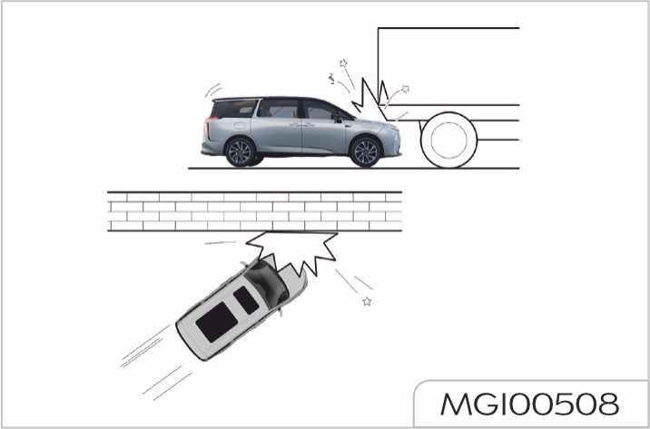
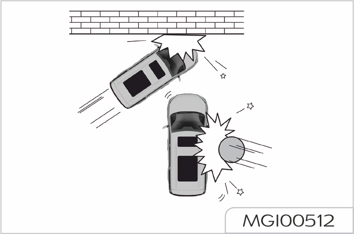
The frontal airbag is designed to deploy in the event of front impact or similar collision. The airbag will deploy under any of the following situations or similar situations.
Side airbag and driver seat farend side airbag
The structure and material of seat is critical for the operation of airbag. Therefore, do not install the seat cover, which will affect the deployment of side airbag.
In case of serious side impact, the front seat side airbag on the side subject to impact will pop out from the seat cover and deploy rapidly. The side airbag on the side not subject to impact will not deploy. The side airbag will deploy under any of the following situations or similar situations.
Side air curtain
In case of serious side impact, the side air curtain on the side subject to impact will pop out from the headliner and deploy rapidly. The side air curtain on the side not subject to impact will not deploy. The side air curtain will deploy under any of the following situations or similar situations.
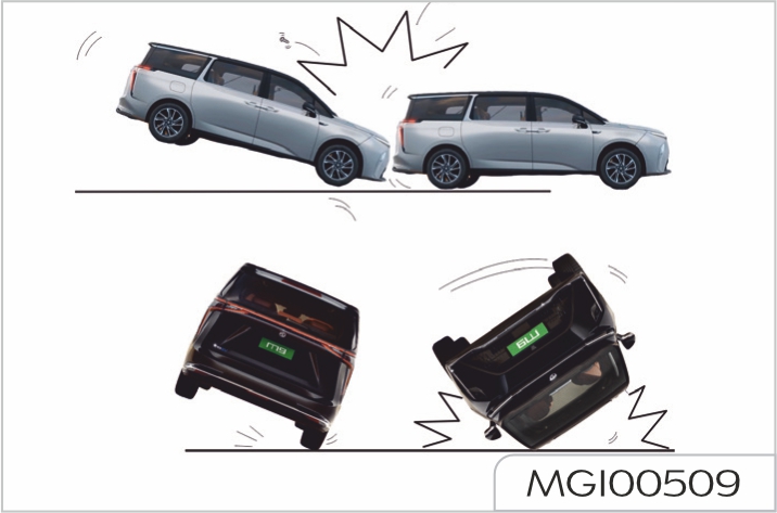
Conditions for airbag undeployment
Airbag will deploy based on the crash object, direction and vehicle deceleration caused by crash rather than vehicle speed.
When the impact force of crash is absorbed or dispersed on the vehicle body, the airbag may not deploy; but based on the impact condition during the accident, the airbag may sometimes explode. Therefore, damage severity of vehicle shall not be considered as the judgment of airbag deployment.
Frontal airbag
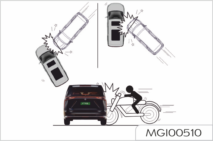
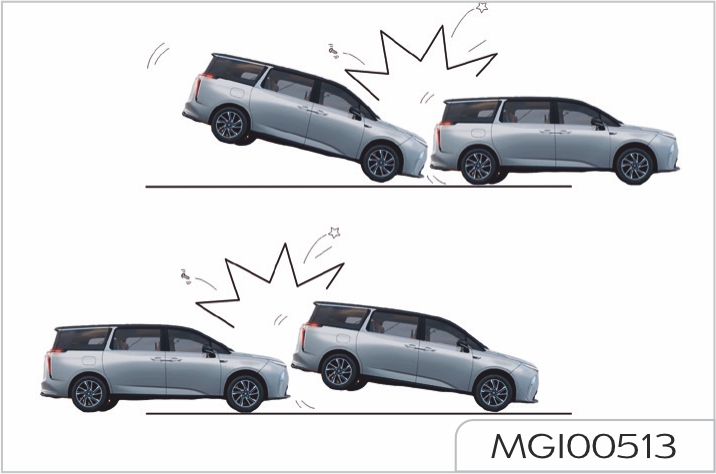
The side airbag may not deploy under any of the following situations or similar situations.
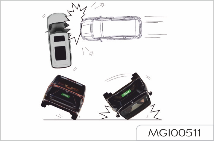
Side airbag, driver seat far-end side airbag and side air curtain
The side airbag and side air curtain may not deploy under any of the following situations or similar situations.
Replace airbag system components after a collision accident
The airbag system could be damaged due to a collision accident. Thus the airbag system cannot operate normally to protect you and occupants in future collision accidents resulting in serious injury even death. To ensure the airbag system remains valid after a collision accident, consult Our Service Dealer to make inspection and necessary replacement of components.
Once the airbag is inflated, it is required to replace the components of the airbag system. Contact Our Service Dealer for service as soon as possible.
Event data recorder (EDR)
This vehicle is equipped with an event data recorder (EDR). The main function of EDR is to record the data of vehicle movement and safety system status within a short time during collision or near collision, which can be used to reproduce the state of the vehicle before, during and after collision, such as vehicle speed, accelerator pedal opening, and brake pedal depth. The EDR data extraction tool reads data based on the 11-bit CAN identifier, and reads the EDR data by using the 2216 "Reading data service by data identifier" service in 11.2 of ISO 14229-1:2020 by means of physical addressing. The data can be read from the airbag controller with our dedicated after-sales scan tool. You can log in to the corresponding link of our official website to purchase the EDR data reader.
General points relating to child seat
Although one of our company's main criteria when designing your vehicle, the safety of your children also depends on you.
May result in death or serious injury!
Observe the instructions provided by the infant or child restraint device's manufacturer if you are installing or using such device.
WARNING: child restraint anchorages are designed to withstand only those loads imposed by correctly fitted child restraints. Under no circumstances are they to be used for adult seatbelts, harnesses, or for attaching other items or equipment to the vehicle.
For maximum safety, please observe the following recommendations:
We recommends that children should travel on the rear seats of your vehicle:
The regulations on carrying children are specific to each country. Refer to the legislation in force in your country
Below are instructions must be followed when using a child seat on the front passenger seat
Rearward facing
The front passenger airbag must be deactivated when using a rear-facing child seat on the front passenger seat. Once the rear-facing child seat is removed from the front passenger seat, the front passenger airbag must be activated immediately.
If needed, adjust the front passenger seat to its fully rear position to avoid the interaction between the child seat and IP facia.
Forward facing
If needed, adjust the second row or third row seat to its fully rear position and its seatback angle when installing the child seat on it.
If needed, adjust any front passenger seat (fore/aft) in case there is an interaction between the child seat/ child and the respective front seat.
Adjust or remove the head restraint when installing the child seat so that the passenger seat or head restraint provides full support to the child seat.
Ensure that the vehicle belt passes through the fitting guide attached to the child seat without getting tangled or bending.
A child seat with a support leg must never be installed on the centre rear passenger seat.
If the center seat of second row can available, the same as the outside adjustment.
Locations for child seats secured using the seat belt
This table indicates the options for Installing child seats secured using the seat belt and universally approved in relation to the weight of the child and the seat in the vehicle.
| Seat | Mass Group | ||||
|---|---|---|---|---|---|
| Group-0/0+ Up to 13kg | Group-1 9 to 18 kg | Group-2 15 to 25kg | Group-3 22 to 36kg | ||
| Row 1 | Passanger Seat | X | X | X | X |
| X | X | X | X | ||
| Row 2 | All Seats | U | U | U | U |
| Row 3 | Oughter Seats | U | U | U | U |
| Center Seat | U | U | U | U | |
|
U: seating position suitable for the installation of a child seat secured using the seat belt and approved for the universal use rearward forward-facing and/or forward-facing. UF: Seating position suitable for the installation of a child seat secured using the seat belt and approved for universal use forward-facing. X:Seating position not suitable for installing a child seat for the weight group indicated. |
Remove and stow the head restraint before installing a child seat with a backrest on a passenger seat. Refit the head restraint once the child seat has been removed.
When installing a CRS on the front passenger seat, the below instructions can be followed if needed:
When installing a CRS on the second row or third row seat, the below instructions can be followed if needed:
Adjust the second row or third row seat to its fully rear position when installing the child seat on it.
"ISOFIX" mountings
Your vehicle has been approved in accordance with the latest ISOFIX regulation.
ISOFIX mountings:
If the center seat of second row can available, the same as the outside adjustment.
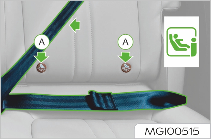
- Two rings A, located between the vehicle seat back and cushion, indicated by a marking.
For information on the possibilities for installing ISOFIX child seats in your vehicle, refer to the summary table.
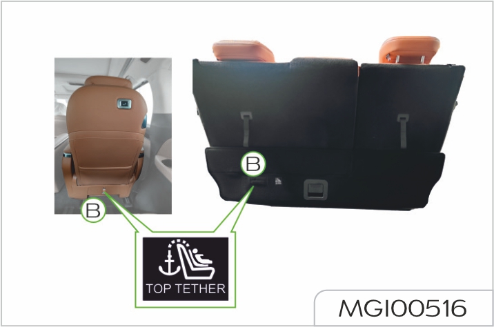
- One ring B behind the seat and identified by a marking, referred to as the Top Tether for fixing the upper strap.
Allows for an extension strap to be used, if the length of the CRS strap (in some cases for rearward facing CRS) is not long enough to reach the anchorage.
To secure the child seat to the TOP TETHER:
- Remove and stow the head restraint before installing the child seat on the seat (refit it once the child seat has been removed).
- Pass the upper strap of the child seat behind the seat backrest, between the apertures for the head restraint rods.
- Fix the hook of the upper strap to the ring B.
- Tighten the upper strap
When fitting an ISOFIX child seat to the left-hand of the third row seat, before fitting the seat, first move the center rear seat belt towards the middle of the vehicle, to avoid the seat interfering with the operation of the seat belt.
The incorrect installation of a child seat in a vehicle compromises the child’s protection in the event of an accident. Follow strictly the fitting the instructions provided with the child seat.
Locations for ISOFIX child seats
This table indicates the options for installing ISOFIX child seats on seats in the vehicle fitted with ISOFIX mountings.
| Seat | Mass Group | ||||
|---|---|---|---|---|---|
| Group-0/0+ Up to 13kg | Group-1 9 to 18 kg | Group-2 15 to 25kg | Group-3 22 to 36kg | ||
| Row 1 | Passanger Seat | X | |||
| X | |||||
| Row 2 | All Seats | IL | IL | IL | IUF/IL |
| Row 3 | Left Oughter Seat | IL | IL | IL | IUF/IL |
| Right Oughter Seat | X | ||||
| Center Seat | X | ||||
|
IUF: :seating position suitable for the installation of an lsofix Universal seat forward facing secured using the upper strap.IL:seating position suitable for the installation of an lsofix SemUniversal seat either:
For securing the upper strap using the ISOFIX mountings, refers to the corresponding section. X;seating position is not suitable for the installation of an ISOFIX seat or a cot of the weight group indicated. |
Remove and stow the head restraint before installing a child seat with a backrest on the passenger seat. Refit the head restraint once the child seat has been removed. When installing the child seat, the below instructions can be followed if needed:
Locations for i-Size child seats
The i-Size child seats have two latches that engage on the two rings A. The i-Size Child seats also have:
The rote of which is to prevent the child seat from tipping forward in the event of a collision.
For more information on ISOFIX mountings, refer to the correspondtng section.
This table indicates the options for installing i-Size Child seat on seats In the vehicle fitted with ISOFIX mountings approved for i-Size.
| Seating Position | i-Size restrain system | |
|---|---|---|
| Row 1 | Passanger Seat | X |
| X | ||
| Row 2 | All Seats | i-U |
| Row 3 | Left Oughter Seat | i-U |
| Right Oughter Seat | X | |
| Center Seat | X | |
|
i-U: sultable for i-size restraints of the "universal" category, forward facing or rearward facing. i-UF: only suitable for i-Size restraint systems in the "Universal" category forward facing. X: seating position not suitabae for i-Size restrain systems in the "Universal" category |
Remove and stow the head restraint before installing a child seat with a backrest on the passenger seat.
Refit the head restraint once the child seat has been removed. When installing the child seat, the below instructions can be followed if needed:
Dual brake hydraulic system
A failure in one of the hydraulic pipelines will be indicated by illumination of the "braking system warning light (red)" on the instrument cluster while driving; it will result in increased brake pedal travel and effort, longer braking distance and may cause the vehicle to pull to one side. Do not pump the brake pedal in an attempt to restore pedal pressure. If there is pressure failure in one of the brake pipelines, the cause must be investigated. IMMEDIATELY bring the vehicle carefully to a halt. Immediately contact Our Service Dealer for service. Do NOT continue driving.
Should one of the hydraulic pipelines fail the other circuit will continue to function.
General state
Always ensure that floor mats or other objects do not disturb brake pedal movement.
Never rest your foot on the brake pedal as this may overheat the brakes, reduce their efficiency and cause excessive wear. If brake pads/shoes have worn excessively, a squealing or screeching noise will be heard when the brakes are applied, and braking efficiency will be affected. Contact Our Service Dealer for service as soon as possible.
If the motor stops running due to some causes, brake booster will stop working after 2 pedal operations; to achieve the expected brake effect, a larger force shall be applied on the pedal. In these circumstances the braking distance may be longer.
If the vehicle is not in regular use or is garaged for long periods, the efficiency of the braking system could be impaired. Contact Our Service Dealer for service as soon as possible.
Wet state
Driving in heavy rain and slushy roads will considerably reduce braking efficiency. At this time, keep safe distance from other vehicles and gently depress the brake pedal intermittently to dry the brake friction components. In severe wet weather, this drying process may need to be repeated every few miles.
In winter, ice can form or salt may accumulate on the brake pads and discs. Ice and salt accumulation will be cleaned off after intermittently light applications of the brake pedal.
Descending steep hills
Overheating the brakes will reduce braking efficiency and may also cause the vehicle to pull to one side.
ABS is used to prevent the road wheels from locking under emergency braking, thereby helping you maintain steering control. No special driving technique is needed.
Under normal braking (where sufficient road surface friction exists to prevent wheel lock), the ABS will not be activated.
An integral feature of this braking system is Electronic Brake Distribution (EBD), which is used to optimize the braking force at the rear wheels under full load condition.
Important rules for emergency brake with ABS On:
ABS Function
ABS may not be able to shorten the brake distance, depending on road surface conditions, brake distance may vary significantly. In fact, when the vehicle without ABS drives on some roads (e.g., gravel road or snowy road), the brake distance may be shorter.
ABS cannot overcome the physical limitations of stopping your vehicle in too short a distance, cornering at high speed, or aquaplaning, i.e. where a layer of water prevents adequate contact between the tyres and the road surface.
ABS must never tempt you to take risks that could affect your safety or that of other road users. You still have a duty to drive within normal safety margins, having due consideration for the road surface, weather and traffic conditions.
If the braking force you use exceeds the available adhesion between the tyres and the road, causing one or more wheels to be locked, then ABS will automatically come into operation.
You will hear the sound of a rapid pulsation which will also be felt through the brake pedal.
When braking in an emergency, always depress full force to the brake pedal, even if the road surface is slippery. ABS is activated; it constantly monitors the speed of each wheel and varies the braking pressure to each according to the amount of friction available.
This prevents the wheels from locking and enables steering control to be maintained.
Precautions for driving a vehicle with ABS
Functions of ESC
ESC covers the functions of ABS, EBD, TCS, VDC, HBA, RMI, HHC, AUTO HOLD and HDC.
ESC indicator on the instrument cluster flashes when the ESC is operating. You may hear some noise or feel the vibration of brake pedal, which is normal.
When the vehicle is powered on, "ESC indicator (yellow)" will illuminate and go off after several seconds. In normal driving conditions, ESC indicator keeps off, and ESC is in monitoring state. When the ESC indicator flashes, it indicates ESC is operating. You may hear some noise or feel the vibration of brake pedal, which is a normal phenomenon. In case of ESC failure, ESC indicator will stay On. Please take the vehicle to Our Service Dealer for ESC inspection.
ESC switch is located on the central control screen, ESC can be turned off with ESC OFF button, and when ESC function is turned off, "ESC OFF indicator (yellow) " illuminates and only ABS and EBD functions are available.
EBD (Electronic Brake-force Distribution)
EBD automatically detects the grip conditions between wheels and ground, distributes the brake force optimally to 4 wheels, so as to improve brake efficiency and driving stability.
TCS (Traction Control System)
TCS automatically controls the driving force at the start-off and acceleration to prevent wheels from spinning, so as to maintain the driving stability
VDC (Vehicle Dynamics Control)
VDC is an advanced computer system, which can help you to control the vehicle driving direction in severe driving conditions.
When the computer detects the deviation between the expected driving route and the actual driving direction, VDC system may selectively apply brake pressure on one or more brakes of the vehicle so as to keep the vehicle driving in the direction commanded.
HBA (Hydraulic Brake Assist)
In case of emergency braking, usually the driver can step on the brake pedal quickly, but the braking force may not reach the maximum deceleration that the vehicle and the ground can provide. HBA function supports to provide additional braking force in such emergency braking conditions.
RMI (Roll Movement Intervention)
RMI can identify the vehicle rollover trend as early as possible by monitoring the turning angle of steering wheel and lateral acceleration, and apply braking to one or more wheels to prevent the rollover to the greatest extent.
HHC hill hold control
When the vehicle drives uphill, HHC can prevent the vehicle from sliding backwards after the driver releases the brake pedal.
An interval up to 2 seconds is available for the driver to shift his foot from the brake pedal to the accelerator pedal so as to successfully drive off on a slope
AUTO HOLD
The ESC runs together with the EPB to help your vehicle park in any stationary condition without depressing the brake pedal all the time.
HDC (Hill Descent Control)
When the vehicle is running downhill, the HDC function can help the driver keep the speed constant, allowing the driver to focus just on the steering wheel.
Precautions for driving a vehicle with ESC
ESC can detect and analyze vehicle conditions, and take preventive measures by correcting wrong driving operation.
However, anything has its limit and no safety device is absolutely safe if the driver blindly drives the vehicle overspeeding.
The EPB pull-up switch is integrated with the P button on the shift lever. When the vehicle is stationary, press the P button to put the vehicle into P gear while the EPB is pulled up, and there is also an EPB release switch on the center console screen.
Instructions before Using EPB
Parking
Manual Hold
Start-of
Manual Release of EPB
Automatic Release of EPB
If a gear is engaged when the vehicle is stopped and the motor is running, never depress the accelerator pedal. Otherwise, the vehicle will immediately move on its own and an accident may occur.
Emergency Braking Function
When the vehicle is in motion, press the P button on the shift lever to activate the emergency braking function. At this time, the vehicle will brake four wheels by activating
the hydraulic brake system, and its braking effect is just like pressing the brake pedal hard. As long as the P button is released, the emergency braking function will be deactivated.
The function is usead when the normal braking operation has failed.
Automatic EPB pull-up function
EPB (Electronic Parking Brake) has Complete power-off automatic pullup function. You can select to enable the EPB power-off automatic pull-up function on the central control screen by the switch titled "Auto Activate EPB when POWER - OFF". This function is enabled by default, that is, EPB will be automatically pulled up when the vehicle is completely powered off. If you select to disable this function, it will take effect only in current ignition cycle. In next ignition cycle, this function will automatically restore as enabled.
Refer to the following processes for the operation steps:
When the function is disabled, be sure to park the vehicle on flat ground to ensure safe parking.
AUTO HOLD is located on central control screen. Use this switch to control the on or off of AUTO HOLD system.
The AUTO HOLD system supports the driver to reduce driving fatigue when the vehicle often encounters traffic lights or stops and goes repeatedly. The Auto Hold function enables the parking brake to release automatically when starting off, and the vehicle to park automatically when it is stationary.
AUTO HOLD ON
These conditions may required to enabled AUTO HOLD function: the driver's door is closed; the driver's seat belt is fatened; the motor is started.
When the AUTO HOLD switch is turned on, the "AUTO HOLD indicator (gray)" on the instrument cluster will illuminate. When the vehicle is stationary and the "AUTO HOLD indicator (green)" on the instrument cluster illuminates, if AUTO HOLD is operating, first perform ESC to hold pressure and stop vehicle. 10 minutes later, if the vehicle is still in stationary state, ESC will request for EPB. The "AUTO HOLD indicator (gray)" goes out, and the "EPB indicator (red)" illuminates.
During operation of the AUTO HOLD, opening the door or unfastening the seat belt will activate the EPB. The "AUTO HOLD indicator (gray)" goes out and the "EPB indicator (red)" illuminates.
If you depress the accelerator pedal as usual, the parking brake will be automatically released and the vehicle will start.
The "AUTO HOLD indicator (gray)" on the instrument cluster illuminates, and the AUTO HOLD is in standby state.
Disable AUTO HOLD
When the AUTO HOLD switch is turned off, the "AUTO HOLD indicator (gray)" on the instrument cluster will go out, and the AUTO HOLD function is disabled.
Do not perform auto hold on the road with the slope more than 30%, otherwise the vehicle may slip.
When the "AUTO HOLD indicator (yellow)" on the instrument cluster illuminates, it means the AUTO HOLD system is faulty, please drive immediately to Our Service Dealer for vehicle inspection.
When driving on a long downhill road with a relatively great gradient, if the vehicle speed is within a certain speed range, there is no need for the driver to depress the brake pedal and accelerator pedal, and the vehicle will run at a low speed automatically, so as to ensure the vehicle goes downhill steadily; at this time, the driver can correct the automatically controlled speed of system through brake pedal and accelerator pedal.
HDC is located on central control screen. Use this switch to control the on or off of HDC system.
When the vehicle speed is within the range of 35 - 60 km/h, HDC is inoperative but in standby state.
When the vehicle speed is higher than 60 km/h, HDC function automatically exits. To enable it again, you need to press the HDC switch on central control screen again.
When the vehicle is powered on, HDC function is disabled by default. When the HDC switch is turned on, "HDC indicator (green)" on the instrument cluster illuminates, and HDC function is in standby state. When HDC operates, "HDC indicator (green)" will flash; if "HDC indicator (yellow)" illuminates, it indicates the HDC system is faulty. Please drive the vehicle to Our Service Dealer for ESC system inspection.
When the HDC switch is turned off, the "HDC indicator (green)" on the instrument cluster will go out, and the HDC function is disabled.
HDC function is used to assist the driver to go downhill steadily at a low speed, and it is not recommended to enable this function on a non-ramp road.
Warning lights related to braking system include "braking system warning light (red)", "ABS warning light (yellow)", "EBD warning light (red)", "ESC indicator (yellow)", "ESC OFF indicator (yellow)", "EPB indicator (red)", "EPB malfunction warning light (yellow)", "AUTO HOLD indicator (gray)", "AUTO HOLD indicator (green)", "AUTO HOLD indicator (yellow)", "HDC indicator (green)" and "HDC indicator (yellow)", please see "Warning lights and indicators" in Before You Drive section.
The vehicles with electronic control booster is preset with two brake pedal sensing mode: "standard" and "sports", and the driver can select and switch between these two modes on the central control screen.
When the "sports" modes is selected, a small pedal force or pedal stroke can not only obtain larger braking force, but also reach the maximum point of booster force in a short time and shorten the braking distance. This mode is applicable to old or female drivers with small stepping force.
When the "standard" mode is selected, the braking force output is relatively moderate at the same pedal force or pedal stroke, which is applicable to the vast majority of people.
When switching brake pedal sensing mode, ensure that the vehicle starts from a stationary state and the brake pedal cannot be stepped on.
If the electric power steering fails or cannot operate, the steering will appear very heavy, which will affect driving safety.
The electric power steering system only works when the vehicle is started. The system operates via a motor with assistance levels automatically adjusted based on vehicle speed, steering torque and steering wheel angle.
The electric power steering system has the advantages of simple structure and energy saving. Compared with the traditional hydraulic power steering system, the electric power steering system only needs energy in actual steering, so that power loss can be reduced in this operating way of power consumption according to the need.
When the electric power steering system operates, holding the steeing wheel on full lock for long periods will result in a reduction in power assistance and cause a heavier feel to the steering.
EPS (Electric Power Steering) system malfunction warning light
See "Warning lights and indicators" in Before You Drive section.
If the battery is disconnected or lacks power seriously, this light may illuminate. At this point, fully turn the steering wheel to the left then the right, thus the system initialization is completed, and the light will go out.
Do not adjust the steering wheel position during driving. This is extremely dangerous.
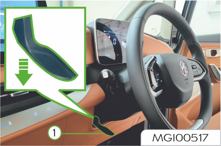
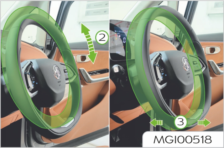
Adjust the steering wheel position to adapt to your driving posture through the following steps:
Be Sure you have read the "Before You Drive" section of this Handbook and a good understanding of your vehicle and it's equipment before reading this section.
Power on vehicle
Unlock the vehicle with key. When the driver door is opened, the vehicle can be powered on automatically.
Start vehicle
The vehicle not started can be started when meeting the following conditions.
Power off vehicle
The vehicle is stationary, the gear is switched to P, you leave the vehicle, close the driver's door, lock the vehicle, and the vehicle power is turned off.
Automatic power off
With the vehicle kept stationary, switch the gear to P gear without stepping on the brake pedal, and the vehicle will automatically be powered off 2 hours later; if the “No Power-off for Temporary Parking” mode is enabled, the vehicle power will not turn off after locking the vehicle.
Emergency power off
When the vehicle is kept stationary, if it needs to be powered off in emergency in case of sudden conditions, please long press the hazard warning light switch for 5s, or press it for 5 consecutive times in 3s to turn off the vehicle power supply.
When the vehicle is running, if it needs to power off the vehicle in emergency in case of sudden conditions, please step on the brake pedal while pressing the hazard warning light switch for 5 consecutive times in 3s to turn off the vehicle power supply
Slow charging is generally recommended for the vehicle; frequent use of fast charging should be avoided.
Check will be conducted to confirm whether the inlets and jacks are in good condition or not before charging.
It is recommended that the charging connector should be connected to the charging inlet in the body before operating the charging equipment.
After charging, turn the power of the charging equipment off first, then disconnect the charging connector from the charging inlet in the vehicle body, and close the charging inlet cover as well as the charging port panel on the body.
When the charging pile breaks down, immediately notify the relevant professional, and the operator cannot handle it without authorization.
Charging can be conducted in rainy days, but rainproof measures will be adopted for charging connector and charging port in the process of removing and inserting charging connector.
Charging operation need be stopped in extreme weather such as storm.
Basic principles
Basic principles
Requirements for over-current protector (air switch)
Requirements for circuit cable
Requirements for household socket outlet
Miscellaneous
When conducting fast charging, the operation area may have magnetic field interference. It is recommended that users who carry implantable heart pacemaker and implantable angiocarpy defibrillator keep away from vehicles under charging.
Magnetic field interference may affect normal effect of electronic medical equipment such as implantable heart pacemaker and implantable angiocarpy defibrillator. Users who carry implantable heart pacemaker and implantable angiocarpy defibrillator may be injured or die.
If you carry implantable heart pacemaker and implantable angiocarpy defibrillator, please guarantee when vehicle is under charging operation:
When the vehicle does not conduct charging operation, special personnel can ride and drive vehicles.
Charging pile DC charging (fast charging)
Use the public DC charging piles to charge your vehicle. Please refer to the following table and attached drawings. The label on the vehicle charging port indicates that the vehicle supports the fast charging shown in the following table.
Household single-phase AC charging (slow charging)
Connect the vehicle to a household standard household socket to charge the vehicle, if the socket is not well grounded, the charging device will have a failure prompt for unable to charge.
You need to contact a professional electrician to repair the ground wire or connect it to a well-grounded socket for charging.
Check the power socket in the process of charging. If it is hot, do not continue to use it. Contact a qualified electrician for servicing the power socket.
Always use the standard household socket which meets the provisions in IEC 60884 for charging.
If a 'Electric Leakage' prompt is displayed, contact a professional electrician to check the insulation status of the hot wire or the neutral wire.
Special power sockets should be selected for battery charging, as they can prevent line damage and protection trip caused by high-power charging from affecting the normal use of other equipment. Over time, the power socket may wear out due to normal use and may even be damaged, making it no longer suitable for charging an electric vehicle.
When used outdoors, plug it into a power socket that is protected from rain.
Charging pile AC charging (slow charging)
Use the public AC charging piles to charge your vehicle
Please refer to the following table and attached drawings. The label on the vehicle charging port indicates that the vehicle supports the slow charging shown in the following table.
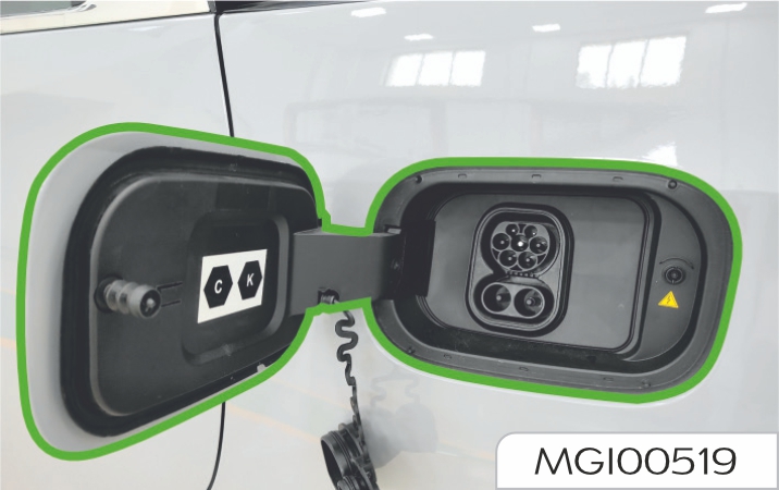
| Configuration | Type of accessory | Voltage Range | Identifier |
|---|---|---|---|
| TYPE 2 | Vehicle inlet | ≤ 480V RMS | C |
| FF | Vehicle inlet | 50V - 500V | K |
Fast charging should be conducted by the personnel in the fast charging station according to the operation instructions for charging pile.
To perform a fast charging for the vehicle, turn off the vehicle
power, wait for 3-5 minutes, and then follow the instructions below:
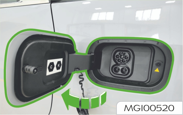
Connect the charging connector to the charging equipment, and turn the power of the charging equipment on according to the instructions on the charging pile.
Before charging, check whether there is any abnormality in the charging equipment. In the charging process, the "charging status indicator (yellow)" on the instrument cluster illuminates. If the equipment can not be charged after 3 consecutive attempts, it is recommended to replace other equipment for attempts.
If the equipment can be charged after replacement, the previous charging equipment may be damaged.
Please check whether the PP and CP pins of the charging connector are rusted. If so, please clean them before charging to prevent charging failure.
After the charging connector is properly connected, the "charging connection indicator (red)" on the instrument cluster will come on.
Please make sure that the charging connector is fully inserted into the charging stand to avoid that the electronic lock cannot be locked, resulting in charging failure, as shown below.
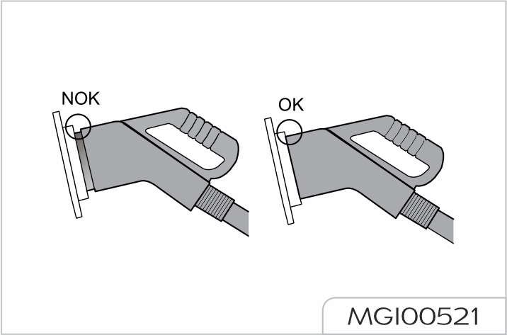
Select a standard DC charging pile or charging equipment that matches your vehicle. Once the battery is fully charged, the battery management system will have an automatic calibration function. If the vehicle has been shallowly charged (less than 99%) every two or three times, you need to fully charge (100%) the vehicle once.
There are three ways to slow charge. The charging method on your vehicle depends on the actual configuration of your vehicle.
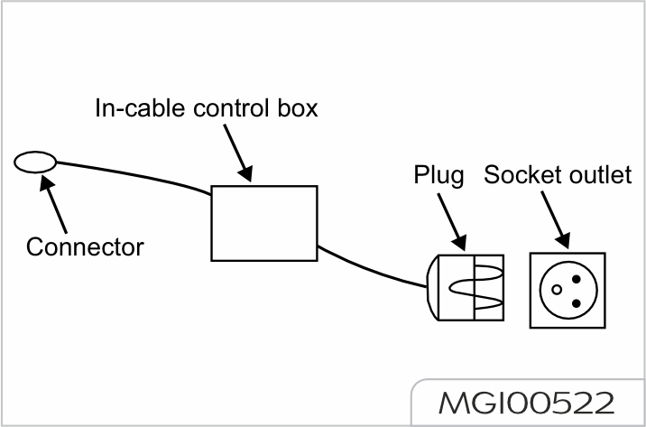
The LED Words on the In-cable control box are as follows:
| Charging Status | Status Description | |||
|---|---|---|---|---|
| Power(Green) | Charging(Red) | Fault(Red) | Complete(Green) | |
| Initial State | On | Flash | Flash | Flash |
| To be connected | On | On | Off | Off |
| Normal Charging | On | Off | Off | On |
| Charging complete | On | Off | Off | On |
| Power-on self-test failed | On | Off | Flash | Off |
| Abnormal Communication | On | On | Flash | Off |
| Over/under voltage | on | Off | on | Off |
| Undergrounded | On | Off | On | Flash |
| Over current | On | Flash | On | Off |
| Current Leakage | On | Off | Flash | Flash |
| Over Temperature | On | On | On | On |

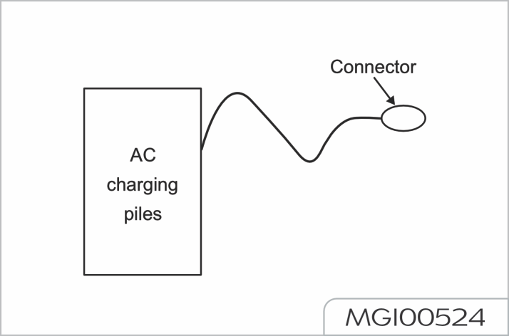
Slow charging is a way of charging high-voltage battery pack to reach the optimal equilibrium state.
To perform a slow charging for the vehicle, turn off the vehicle power, wait for 3-5 minutes, and then follow the instructions below:
• British standard socket.
• German standard socket.
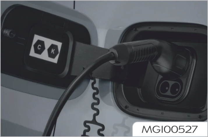
After the charging connector is properly connected, the "charging connection indicator (red)" on the instrument cluster comes on and the electronic lock of the charging inlet is enabled, which guarantees that the charging connector will not be unplugged whilst charging.
Please make sure that the charging connector is fully inserted into the charging stand to avoid that the electronic lock cannot be locked, resulting in charging failure.
If charging with a public AC charging pile, connect the charging connector to the charging equipment, and charge according to the instructions on the AC charging pile
If charging with a public AC charging pile, before charging, check whether there is any abnormality in the charging equipment. In the charging process, the "charging status indicator (yellow)" on the instrument cluster illuminates. If he equipment cant not be charged after 3 consecutive attempts, it is recommended to replace other equipment for attempts. If the equipment can be charged after replacement, the previous charging equipment may be damaged.
If charging with a public AC charging pile, please check whether the PP and CP pins of the charging connector are rusted. If so, please clean them before charging to prevent charging failure.
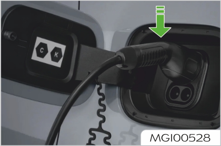
If the charging needs to be ended early and the charging connector be removed, unlock the vehicle with the key, and the vehicle will stop charging automatically. The “Charging status indicator lamp (yellow)” will go out, and the electronic lock will be unlocked automatically
Then, press the button switch on the charging connector to remove it within 1 minute (if the charging connector is not removed within 1 minute, the electronic lock of the charging port will be re-locked).
Emergency treatment: In the event of an emergency such as fire, smoke or burnt smell, turn the socket power switch off immediately to completely power off the system. If the vehicle has been shallowly charged (less than 99%) every two or three times, you need to fully charge (100%) the vehicle once.
Charging inlet emergency cable
The AC charging socket is provided with the electronic lock function. In the charging process, in order to prevent children from touching or unplugging the charging connector by accident, after the charging connector is plugged into the charging socket, the electronic lock in the charging socket will be locked following the master control switch. At this time, do not unplug the charging connector forcefully to avoid causing damage. Be sure to unlock it using a key or master control switch before unplugging. If the charging connector cannot be unlocked with a key or master control switch in an emergency, open the trunk first, remove the left rear side cover of the vehicle, and then pull the emergency cord downward to unlock the charging connector.
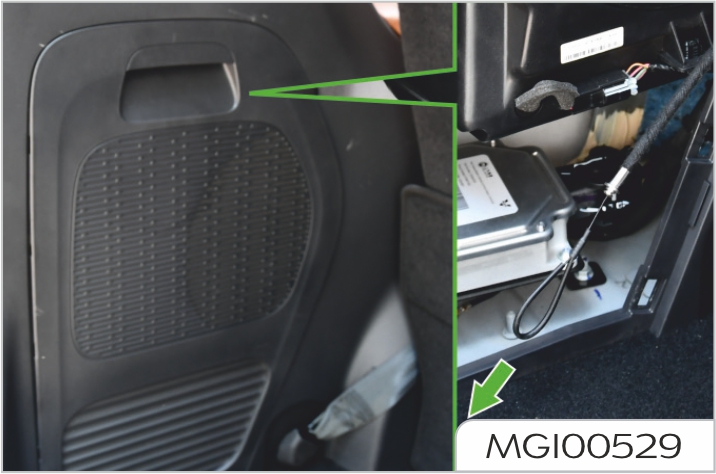
| Sr.No | Charger | SOC Range | Charging TIme | Charger Type(AC/DC) |
|---|---|---|---|---|
| 1 | 3.3 kW | 0 ~ 100% | 34 hrs 22 mins to 34 hrs 30 mins | AC slow charger |
| 2 | 11 kW | 0 ~ 100% | 9 hrs 30 mins | AC fast charger |
| 3 | 60 kW | 0 ~ 97% | 2 hrs to 2 hrs 16 mins | DC fast charger |
| 4 | 120 kW | 0 ~ 97% | 1 hr 28 min to 1 hr 35 mins | DC fast charger |
Equalization charging refers to Battery Management System enabling basically consistent voltages of all battery cells in the charging process to ensure the overall performance of the high voltage battery pack. It is recommended to use the vehicle at least once every month. It is recommended to slowly charge the vehicle for more than 10 hours every month to extend the life of the high voltage battery pack.
For charging safety reasons, the upper limit of DC fast charging capacity is 97%, and the upper limit of AC slow charging capacity is 100%.
It applies to vehicles configured with the charging appointment function.
Charging appointment refers to the user carries out the slow charging at a specified time. The charging appointment function requires that the
function of charging piles is available. Some charging piles do not open the appointment for charging due to the consideration of operational efficiency. In case of brand piles that cannot be appointed for charging, please contact the customer service of the charging piles for consultation or our Service Dealer.
For use of charging appointment function, please follow the following steps:
Charging time of high-voltage battery pack is related to many factors, such as current electric quantity, charging mode, ambient temperature and charging device power.
Fast charging time
Under the normal temperature state, if the charging equipment has an output capacity of over 130 kW, it will take about 40 minutes to charge the highvoltage battery from 20% to 80%.
In order to protect the high voltagebattery pack and to speed up the temperature rise of the battery, when performing a fast charge in a low temperature environment, the high voltage-battery pack may have a drop in capacity for a short period of time, it is normal.
Slow charging time
Under the normal temperature state, it takes about 9.5 hours from the alarm state (the low high-voltage battery pack warning lamp on the instrument cluster illuminates) to the full charge state.
The slow charging time mentioned above means the time required by the vehicle to use AC charging pile for charging. When the residential electricity is used for charging, corresponding charging time will be about 2.5 times of that required for adopting AC charging pile.
It applies to vehicles configured the exterior discharge function.
The discharger and electrical appliances may cause sparks during discharge. In order to avoid accidents, do not discharge at gas stations or places with inflammable gases or liquids.
Follow the instructions below during discharge:
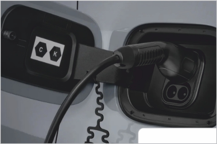
When the battery power is discharged to the set cut-off level, the discharging will be automatically turned off.
Emergency response: If an emergency such as fire. smoke or burnt odor is found during use, tum off the discharge switch immediately to fully cut off the system.
The pure electric vehicle is quiet in low speed driving, resulting in the probability of accidents occurring to pedestrians (especially the blind) higher than that of conventional vehicles. A system making a warning or prompt sound at low speed is achieved via a low speed alarm module (Acoustic Vehicle Alerting System, AVAS) to reduce the probability of accidents occurring to pedestrians. The design of acoustic warning and sound effects for the sound sensitivity of different populations achieves the balance between safety guarantee and noise pollution.
Low speed alarm sound effect
When the vehicle speed is 0-20km/ h, the low speed alarm module simulates the sound of running engine to make the sound alarm, and the tone gradually increases with the acceleration and vice versa, to warn persons outside the vehicle about the vehicle passing. The minimum average frequency shift speed of the frequency meets the requirements of no less than 0.8%/(km/h).
When the vehicle speed is 0km/h, the low speed alarm module does not make a prompt sound.
When the vehicle is reversing, the low speed alarm module simulates the sound of running engine to warn persons outside the vehicle about the reversing state, and the tone gradually increases with the acceleration and vice versa.
When the vehicle reversing speed is 0km/h, the low speed alarm module does not make a prompt sound.
The vehicle is equipped 2 remote keys with passive entry passive start system (hereinafter referred to as PEPS)
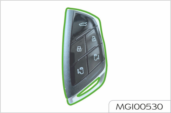
If a key is lost, you must provide the key number on the metal or plastic plate attached with the key, and the Our Service Dealer will provide the replacement. To ensure safety, you are recommended to keep the metal or plastic plate attached with key properly.
For the sake of safety, the key has been electronically coded with the immobilizer system and can be used with the system in the matching way only. Special procedures shall be followed to manufacture a same key with the lost one. Any uncoded key cannot start the vehicle but can lock/ unlock doors.
The remote key is a control component of central door locking system of a vehicle, which can be used for locking/unlocking all doors.
The remote key has been electronically coded with the locking/unlocking system and can be used with the system in the matching way only. Special procedures shall be followed to manufacture a same remote key with the lost one. Our Service Dealer will be pleased to assist you.
See "Central door locking system" in this section for more details about the remote key.
The immobilizer sysytem can accept 4 coded keys at most (for remote keys with PEPS).
Press the release button on the remote key with PEPS, and pull the mechanical key portion from the key body. To retract the mechanical key portion, directly insert it into the body of remote key with PEPS.
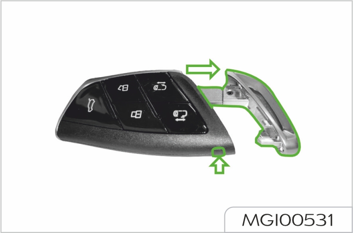
Batteries may present the risk of fire, explosion and burning. Never charge the battery. Properly dispose the used battery. Keep the battery out of reach of children.
Do not ingest the battery, chemical Burn Hazard.
This product contains coin/button cell battery. If the coin/button cell battery is swallowed, it can cause severe internal burns in just 2 hours and can lead to death. Keep new and used batteries away from children. If the battery compartment does not close securely, stop using the product and keep it away from children. If you think batteries might have been swallowed or placed inside any part of the body, seek immediate medical attention.
WARNING
To replace the battery, following procedures must be observed:
Pry off the upper and lower panels of the body; the circuit board may fall off from the upper panel assembly when prying off them, and reinstall them.
Do not damage the circuit board when prying off the upper and lower panels.
Remove the used battery from the lower panel assembly and install a new one.
It is recommended to use a CR2032 battery.
Pay attention to the positive and negative electrodes of the battery.
Refit the upper and lower panels of the battery body, and press their circumference to ensure they are clamped in place.
Do not ignore the waterproof shim and circuit board onto the upper panel of the key body.
Press the mechanical key portion into the key body.
It is complicated to replace the battery in the remote key with PEPS. In order to prevent the key from being damaged due to missassembly or misoperation, you are recommended to have the battery replaced by our Service Dealer.
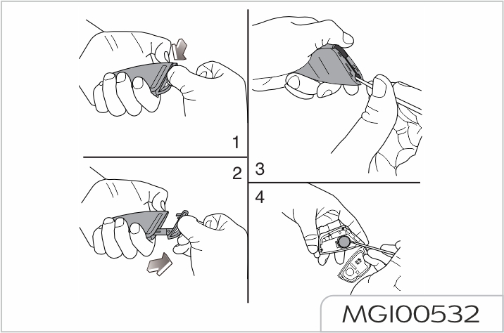
When leaving the vehicle with occupants inside, even briefly, always carry the key and power off the vehicle, particularly if children are left in the vehicle. They could otherwise start the vehicle or operate electrical equipment at the risk of causing an acciedent.
Close all windows before leaving the vehicle. Ensure all doors and hood are fully closed before locking.
Lock/unlock
You may lock/unlock all doors from outside by using the remote key with PEPS.
All doors can be locked/unlocked from the inside using central lock switch. All doors can be automatically locked according to the vehicle speed. See "Central door locking system" in this section.
When all doors are successfully locked by using the remote key with PEPS, all turn signals will flash once, and the horn will sound once to indicate successful locking.
When all doors are successfully unlocked with the remote key, all turn signals will flash twice to indicate successful unlocking.
Using the mechanical key portion
All doors can be locked/unlocked by manually locking/unlocking the driver door using the mechanical key portion from the outside.
To lock, turn the mechanical key portion counterclockwise.
To unlock, turn the mechanical key portion clockwise.
Using the remote key with PEPS
All doors can be locked/unlocked through the central door locking system using the buttons on the remote key with PEPS.
All doors must be fully closed for the system to operate correctly.
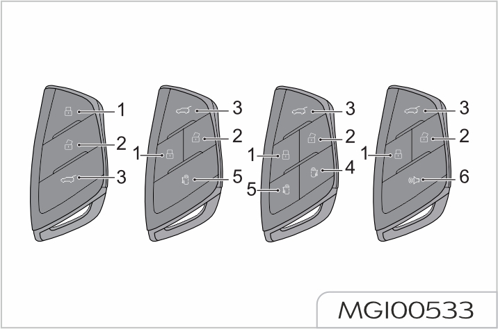
Central locking button (short press)/window up (long press)/ panoramic sunroof closing (long press)
For the functions of window up (long press) and sunroof closing (long press), please refer to your vehicle's actual configuration.
Central unlocking button (short press)/window down (long press)/panoramic sunroof opening (long press) button.
For the functions of window down (long press) and panoramic sunroof opening (long press), please refer to your vehicle's actual configuration.
When locking with the LOCK button
![]() ID on the remote key with PEPS,
if there is another legal remote
key with PEPS in the vehicle, then
the latter key will be disabled, and
the passive entry and one touch
start feature will be lost. To activate
it: close all doors, operate the
unlocking button on the remote key
with PEPS in a normal manner, the
key shielded inside the vehicle will
be activated.
ID on the remote key with PEPS,
if there is another legal remote
key with PEPS in the vehicle, then
the latter key will be disabled, and
the passive entry and one touch
start feature will be lost. To activate
it: close all doors, operate the
unlocking button on the remote key
with PEPS in a normal manner, the
key shielded inside the vehicle will
be activated.
All doors locking
Short press the button
![]() to lock all
doors, provided that all doors have
been closed.
to lock all
doors, provided that all doors have
been closed.
All turn signals flashing once
represents the confirmation
for locking; if the driver door is
not closed, the lock motor will
not operate; if any door other
than the driver door or the front
compartment hood is not fully
closed, the lock motor will operate,
and there will be no audible alarm.
Please close all doors and the
front compartment hood before
pressing the locking button
![]() .
.
Panoramic sunroof closing
Keep pressing ![]() after locking; if
the panoramic sunroof is open,
the panoramic sunroof glass will
automatically close. The maximum
time for long press is 15 seconds.
If the sunroof glass and guide rail
suffer from snow or dirt, they should
be cleaned immediately before long
pressing
after locking; if
the panoramic sunroof is open,
the panoramic sunroof glass will
automatically close. The maximum
time for long press is 15 seconds.
If the sunroof glass and guide rail
suffer from snow or dirt, they should
be cleaned immediately before long
pressing ![]() .
.
For the function of panoramic
sunroof closing by long pressing
![]() , please refer to your vehicle's
actual configuration.
, please refer to your vehicle's
actual configuration.
All doors unlocking
Short press the button ![]() to unlock all doors.
to unlock all doors.
If no door is opened within 30 seconds, all doors will be automatically locked again.
Panoramic sunroof opening
Keep pressing ![]() after unlocking;
if the panoramic sunroof is closed,
the sunshade will be opened to the
half-open position first, and then
the panoramic sunroof glass will be
opened to a comfortable position.
The maximum time for long press is 15
seconds.
after unlocking;
if the panoramic sunroof is closed,
the sunshade will be opened to the
half-open position first, and then
the panoramic sunroof glass will be
opened to a comfortable position.
The maximum time for long press is 15
seconds.
For the function of panoramic
sunroof opening by long pressing
![]() , please refer to your vehicle's
actual configuration.
, please refer to your vehicle's
actual configuration.
Tailgate button
Short press the button ![]() to unlock
the tailgate.
to unlock
the tailgate.
For vehicles equipped with power
tailgate, long press the button ![]() on
the remote key with PEPS to open and
close the power tailgate.
on
the remote key with PEPS to open and
close the power tailgate.
During opening and closing, short
press the button ![]() to stop the
tailgate movement, and long press
the button
to stop the
tailgate movement, and long press
the button ![]() again to reverse the
tailgate movement.
again to reverse the
tailgate movement.
Right electric side load door opening/closing button
After the vehicle is unlocked, when the right electric side load door is closed,
long press the button ![]() to open the
right side load door; during opening,
to open the
right side load door; during opening,
short press the button ![]() to stop
operation of the right side load door;
when the right electric side load door
to stop
operation of the right side load door;
when the right electric side load door
is open, long press the button ![]() to
close the right side load door; during
to
close the right side load door; during
closing, short press the button ![]() to
stop operation of the side load door.
to
stop operation of the side load door.
Left electric side load door opening/closing button
After the vehicle is unlocked, when the left electric side load door is closed,
long press the button ![]() to open the
left side load door; during opening,
to open the
left side load door; during opening,
short press the button ![]() to stop
operation of the side load door; when
the left electric side load door is open,
to stop
operation of the side load door; when
the left electric side load door is open,
long press the button ![]() to close the
left side load door; during closing,
to close the
left side load door; during closing,
short press the button ![]() to stop
operation of the side load door.
to stop
operation of the side load door.
Vehicle locator button
Long press the button ![]() , the vehicle
will emit audible and visual alarm.
, the vehicle
will emit audible and visual alarm.
Using the micro switch
PEPS system allows you to lock or unlock the doors without taking the remote key with PEPS out of your pocket, wallet, or suitcase.
Unlock with the remote key with PEPS
As long as there is a legitimate remote key with PEPS existing within 1 meter around the vehicle, press the micro switch on the door handle, and the door will be unlocked.
Lock with the remote key with PEPS
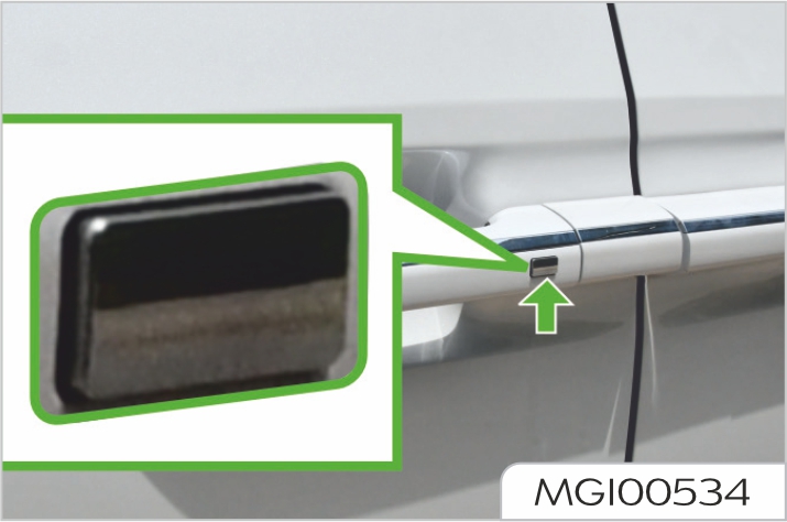
After powering off, leaving the vehicle and closing the door, touch the micro switch on the door handle with your thumb to lock the door, without pressing the lock button on the remote key with PEPS.
Using the central lock switch
All doors can be unlocked or locked
from the inside using the switch. Press
the locking button ![]() to lock all doors.
to lock all doors.
Press the unlocking button ![]() to
unlock all doors.
to
unlock all doors.
If driver door is not closed, the lock motor will not operate. If any other door is not closed, the lock motor will operate.
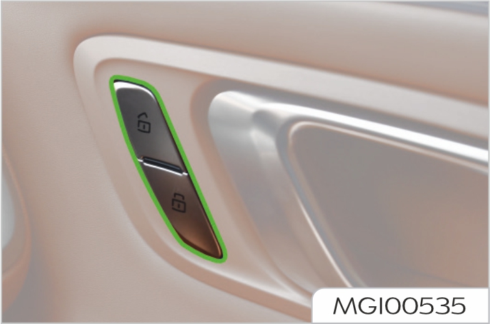
The door can also be unlocked by pulling the inner handle twice.
During the driving, all doors shall be fully closed and all door locks shall be enabled, so as to avoid accidental opening of doors.
Locking according to the vehicle speed
When the vehicle speed exceeds 8 km/h, all doors can be locked automatically under this function.
When the vehicle is powered off, the doors will automatically unlock.
To open the side load door from the outside, unlock the vehicle, and pull up the door outer handle to slide the side load door rearward. To close the side load door from the outside, pull up the door outer handle to slide the side load door forward till it is closed.
To lock from the inside, close the door and push the button (1) towards the front of the vehicle. To unlock from the inside, push the button (1) towards the rear of the vehicle until the red mark is shown.
To open the side load door from the inside, hold the handle (2) and pull it towards the rear of the vehicle after unlocking. To close the side load door from the inside, hold the handle (2) and pull it towards the front of the vehicle.
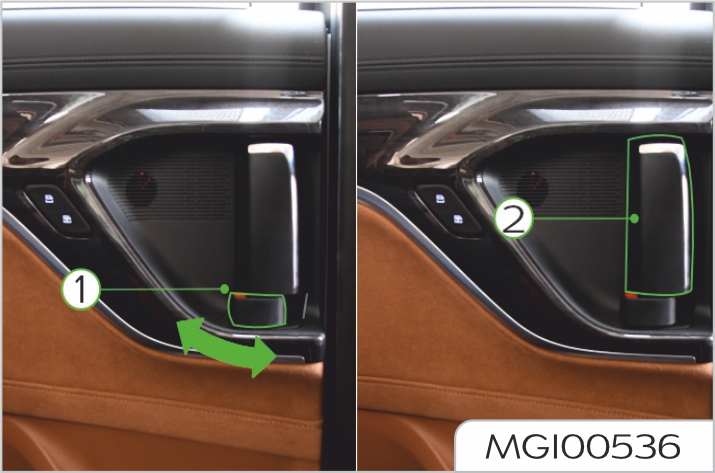
When the charging port door is open, the left side load door should not be opened.
The electric side load door can be opened in multiple ways electrically, and you can open and close the electric side load door according to your vehicle's configuration.
Side load door outer handle
After the vehicle is unlocked, pull up the door outer handle to automatically open the electric side load door. After the electric side load door is fully opened, pull up the door outer handle to automatically close the electric side load door. During automatic opening and closing of the electric side load door, pull up the door outer handle to stop movement of the electric side load door.
After the vehicle is unlocked, long press the micro switch on the door outer handle for 2 seconds to automatically open the electric side load door. After the electric side load door is fully opened, long press the micro switch on the door outer handle for 2 seconds to automatically close the electric side load door
During automatic opening and closing of the electric side load door, short press the micro switch to stop movement of the electric side load door.
When the vehicle is locked, carry a legal key and long press the micro switch on the door outer handle for 2 seconds to automatically unlock and open the electric side load door.
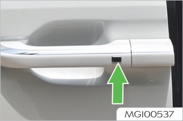
Side load door inner handle
When locking the side load door from the inside, hold the inner handle (2) and pull it towards the front of the vehicle to automatically close the electric side load door. After the electric side load door is closed, push the button (1) towards the front of the vehicle to lock the side load door.
When unlocking the side load door from the inside, push the button (1) towards the rear of the vehicle to show the red mark.
After unlocking the electric side load door, hold the inner handle (2) and pull it towards the rear of the vehicle to automatically open the electric side load door.
During automatic opening and closing of the electric side load door, pull the door inner handle forward or backward to stop movement of the electric side load door.
Electric side load door open/close button on the remote key with PEPS
When the right electric side load door
is closed, long press the button ![]() to
automatically open the right side load
door; during opening, short press the
button
to
automatically open the right side load
door; during opening, short press the
button ![]() to stop operation of the right
side load door; when the right electric
side load door is open, long press the
to stop operation of the right
side load door; when the right electric
side load door is open, long press the ![]() button to automatically close the
right side load vdoor; during closing,
short press the button
button to automatically close the
right side load vdoor; during closing,
short press the button ![]() to stop
operation of the side load door.
to stop
operation of the side load door.
When the left electric side load door
is closed, long press the button ![]() to
automatically open the left side load
door; during opening, short press
the button
to
automatically open the left side load
door; during opening, short press
the button ![]() to stop operation of the
side load door; when the left electric
side load door is open, long press the
button
to stop operation of the
side load door; when the left electric
side load door is open, long press the
button ![]() to automatically close the left
side load door; during closing, short
press the button
to automatically close the left
side load door; during closing, short
press the button ![]() to stop operation
of the side load door.
to stop operation
of the side load door.
This function only can be enabled when the power mode of vehicle is disabled.
Left/right electric side load door switches on front roof vanity light
After the vehicle is unlocked, long press the electric side load door switch on the front roof vanity light for 2 seconds to automatically open the electric side load door. After the electric side load door is fully opened,
long press the electric side load door switch on the front roof vanity light for 2 seconds to automatically close the electric side load door. During automatic opening and closing of the electric side load door, press this switch to stop movement of the electric side load door.
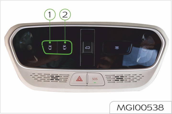
Electric side load door occupant switches at the B-pillar inner trim panel behind the front seat
After the vehicle is unlocked, long press the electric side load door occupant open switch (1) for 2 seconds to automatically open the electric side load door. After the electric side load door is fully opened, long press the electric side load door occupant
close switch (2) for 2 seconds to automatically close the electric side load door. During automatic opening and closing of the electric side load door, press any of the occupant switches to stop movement of the electric side load door.
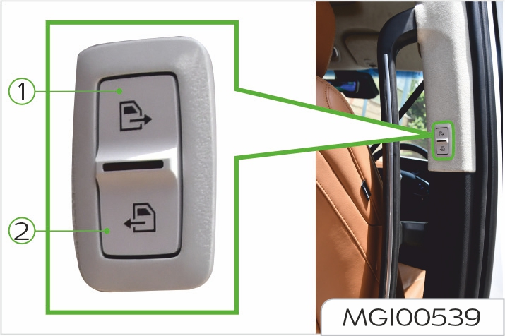
Electric side load door touch buttons on the center console screen
The touch buttons on the center console screen control the opening and closing of the electric side load door.
After the vehicle is powered on, the electric side load door can be opened and closed only when the shift lever is in P gear, the electronic brake is applied or the brake pedal is depressed.
When the charging port door is open, the left side load door should not be opened.
The electric side load door cannot be opened and closed for 10 cycles consecutively. Otherwise, the thermal protection may be enabled. If the thermal protection function of the electric side load door is enabled, please do not operate the electric side load door any more, and wait for 1 minute until the thermal protection function is disabled prior to operation of the electric side load door.
If the side load door encounters any obstacle in the cycle of electric opening or closing, the electric side load door will reverse itself by 10 cm to avoid the obstacle. After the obstacle is removed, the electric side load door can be operated again.
If the side load door encounters some obstacles for 3 times consecutively in the process of electric closing or opening, the electric function will be disabled. After removing the obstacles, close the side load door manually, and the normal electric operation function will be recovered. The anti-pinch sensor is located on the side of electric side load door.
When the electric side load door is closed, if there is any obstacle between the side load door and the vehicle, and the sensor is extruded, the side load door will reserve itself by 10 cm.
When the electric side load door is operating, make sure that there is no person in the path of opening and closing the side load door, otherwise you or other persons may get injured.
If the vehicle is on a ramp of 12° or above, please close the side load door manually for assistance.
If the battery is disconnected or the voltage is too low, the electric side load door cannot be opened.
When the battery is reconnected or charged, the electric side load door will recover normal operation.
Unlocking/opening doors from the outside When using the remote key with PEPS or central lock switch to lock or unlock all doors, the tailgate will also be locked or unlocked.
If the tailgate is unlocked, press the
handle switch ![]() and pull it up to
open the tailgate.
and pull it up to
open the tailgate.
The tailgate will be opened while swinging up. When opening the tailgate, make sure that there are no objects or people near the rear of vehicle.
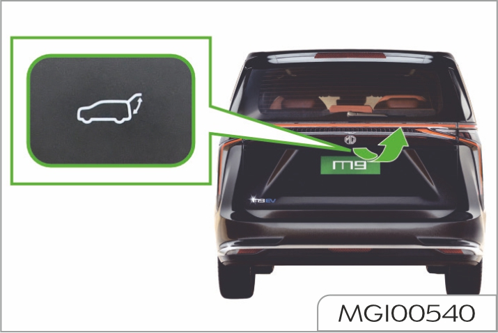
Closing/locking doors from the outside
Make sure that the tailgate has been closed before driving the vehicle. Driving the vehicle with tailgate not closed may result in the damages of tailgate gas strut and other components.
Emergency lock function
The tailgate has the emergency lock function. When the vehicle is powered off or other conditions cause the tailgate to fail, open the cover at the lower end of the tailgate inner trim panel and press the white lever to open the tailgate.
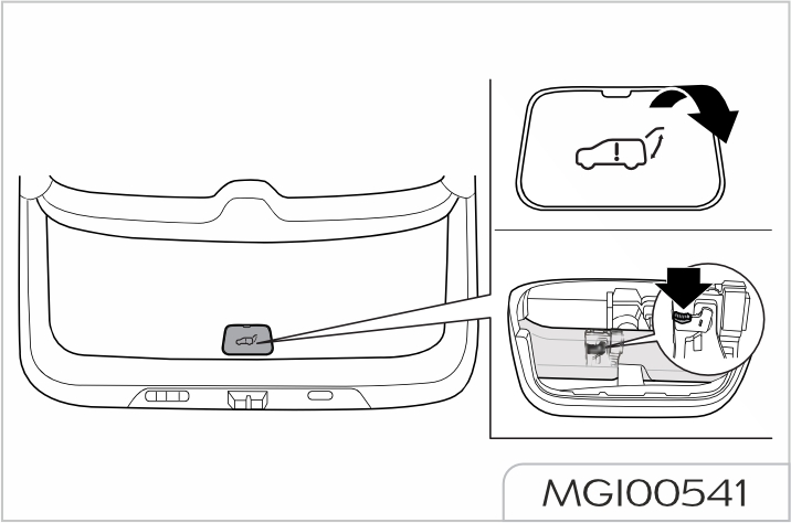
The tailgate will be opened while swinging up. When opening the tailgate, make sure that there are no objects or people near the rear of vehicle. Make sure that the tailgate has been closed before driving the vehicle. Driving the vehicle with tailgate not closed may result in the damages of tailgate gas strut and other components.
The power tailgate can be opened in multiple ways electrically, and you can open and close the tailgate according to your vehicle's configuration.
Tailgate outer panel switch outside the tailgate
After the vehicle is unlocked, press the tailgate outer panel switch to open the tailgate.
After the vehicle is locked, carry the remote key with PEPS within 1 m near the tailgate, and press the tailgate outer panel switch to open the tailgate.
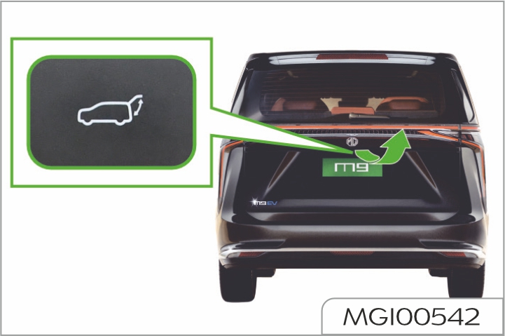
Tailgate inner panel switch inside the tailgate
Press the tailgate inner panel switch to open and close the tailgate. If the tailgate is open, press the tailgate inner panel switch to close the power tailgate. Switch can achieve two-way action, i.e. during the tailgate opening or closing, press the switch to perform reverse action.
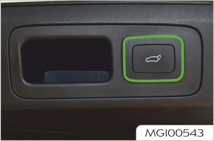
Tailgate switch at the driver door
When the power tailgate is closed, press the tailgate switch at the driver door to open the tailgate; during opening, press the switch to stop the tailgate movement, and press the switch again to reverse the tailgate movement.
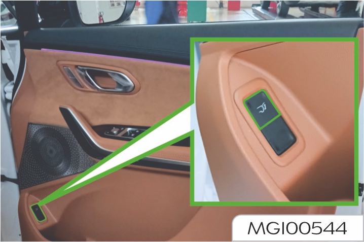
Tailgate unlocking button on the remote key with PEPS
Long press the power tailgate unlocking button on the cremote key with PEPS to open and close the power tailgate.
During opening and closing, short press the button to stop the tailgate movement, and long press the button again to reverse the tailgate movement.
This function only can be enabled when the power mode of vehicle is disabled.
Power tailgate touch buttons on the center console screen
The touch buttons on the center console screen control the opening and closing of the power tailgate and adjust the tailgate opening.
Make sure that the tailgate has been closed before driving the vehicle. Driving the vehicle with tailgate not closed may result in the damages of tailgate gas strut and other components.
When the power tailgate is operating, make sure that there is no person in the path of opening and closing the tailgate, otherwise you or the other person may get injured.
When the tailgate is opened after the vehicle is locked, if you leave the remote key with PEPS in the vehicle and then close the tailgate, the hazard warning light in the vehicle will flash and the tailgate will automatically open. At this time, you should take out the remote key with PEPS and close the tailgate again.
Setting of tailgate opening modes
The power tailgate has three opening modes.
Manual mode
Unlocking is supported, and the tailgate does not automatically open.
Garage mode
When the tailgate garage mode switch button is pressed in the garage mode, the tailgate will be opened to the set garage height. The default opening of the tailgate in garage mode is 75%.
Garage mode setting: Manually open the tailgate to the desired height, and long press the tailgate inner panel switch for 2 seconds until a "beep" sound is heard, indicating that the setting is successful. Press the garage mode switch to open the tailgate to the garage height.
Fully open mode
The fully open mode is the default mode of the vehicle.
Emergency lock function
The tailgate has the emergency lock function. When the vehicle is powered off or other conditions cause the power tailgate to fail, open the cover at the lower end of the tailgate inner trim panel and press the white lever to open the tailgate.
The power tailgate can only be opened and closed at parking gear, which is unavailable at other gears.
If no work instruction is received 15 minutes after the power tailgate is opened, the tailgate enters the sleep mode. If you trigger the switch again, the tailgate will close at a constant speed, and then the normal electric function can be restored.
The power tailgate can not be opened and closed for 10 cycles consecutively. Otherwise, the thermal protection may be enabled. If the thermal protection for the tailgate of your vehicle is enabled, please do not operate the tailgate any more, and wait for 1 minute until the thermal protection is disabled prior to re-operating the tailgate.
If the tailgate encounters any obstacle in the cycle of electric opening or closing, the tailgate will reverse itself to avoid the obstacle. After the obstacle is removed, the power tailgate can be operated again.
If the tailgate encounters some obstacles for 3 times consecutively in the process of electric closing or opening, the electric function will be disabled. After removing the obstacles, close the tailgate manually, and the normal electric operation function will be recovered. The anti-pinch sensor is located on the side of tailgate.
When the tailgate is closed, if there is any obstacle between the tailgate and vehicle, and the sensor is extruded, the tailgate will reserve itself by 5°.
When the power tailgate is operating, make sure that there is no person in the path of opening and closing the tailgate, otherwise you or other person may get injured.
Tailgate servo strategy: when the power tailgate is half-open, it will be closed automatically under any force.
Do not force to open or close the tailgate in the cycle of electric operation.
If the vehicle is on the ramp of greater than 12°, please close the tailgate manually for assistance, and note that the action must be slowly rather than quickly and forcefully
If the battery is disconnected or the voltage is too low, the tailgate will not be opened. When the battery is re-connected or charged, the tailgate will recover to normal operation.
When the power tailgate Is operating, make sure that there Is no person in the path of opening and closing the tailgate, otherwise you or other person may get injured. When you wash your vehicle, ensure the remote key with PEPS is kept away from the rear bumper detection area, as flushing may cause the taigate to open. If the rear bumper is covered with a lot of ice, snow, dirt or similar objects, the tailgate sensitive opening function will weaken or not work, so please keep it clean.
If any child sits in the rear seat, please use the child safety lock.
Your vehicle is configured with a child safety lock on each side load door. These locks are used to prevent the occupants (especially children) from pulling the inner door handle from the inside to open the side load door.
When the child safty lock is in the locking position, do not pull the inner door handel forcefully. Doing so may damage the inner door handel.
To enable the child safety lock:
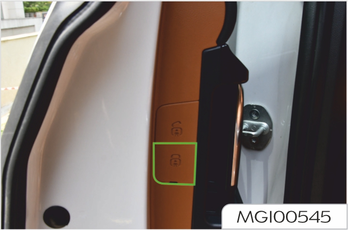
Each side load door has its own lock. The child safety lock of each side load door (either on the left or right) shall be respectively enabled and disabled manually.
After the child safety lock is enabled, the side load door can only be opened by operating the outer door handle from outside. To cancel the child safety lock, push the control lever up to the unlocking position.

When all doors are locked, enter the sensing area with a remote key and press the microswitch on the door handle or tailgate switch, the central lock will unlock automatically. After unlocking, turn signal lamps will flash twice. If you do not conduct any of the following operations within 30s after that, the central lock will automatically lock again:
It is feasible to unlock doors with the central unlocking button on the remote key. Press the central unlocking button once, and the central lock will unlock automatically
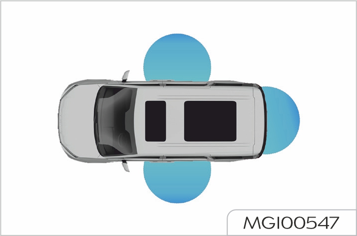
When the driver's door or front passenger door is in unlocked state, enter the sensing area with a remote key, and then press the micro switch on the door handle or the tailgate switch on the trunk lid. The direction indicators will flash once, meanwhile the alarm horn will ring once for a short time (as appropriate).
Then all doors will be locked, meanwhile the vehicle enters the fortification state. In any of the following cases, the doors will not be locked after the micro switch is pressed:
It is feasible to lock doors with the central locking button on the remote key. Press the central locking button once, and the central lock will lock automatically.
When the key is in the vehicle, the front compartment hood closed, the shift lever in P or N gear, step on the brake pedal to start the vehicle.
When the remote control battery is low, the keyless entry function will fail, but you still can start the vehicle. Open a door with the mechanical key and enter the vehicle. At this time, the system may be in IMMO state and the alarm may be triggered, which is a normal situation.
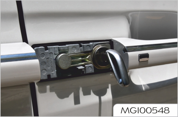
With the shift level in P or N gear, place the remote key in the cup holder with a symbol on the auxiliary fascia console, and step on the brake pedal to start the vehicle. In this case, the system will release IMMO.
Type 1
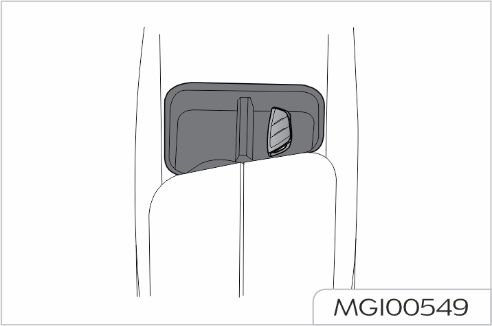
Type 2
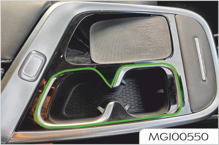
When driving, never place any portable container with fuel on the vehicle. Otherwise it may leak and a fire may result.
Skid
If your vehicle skids on a wet road, you cannot control the vehicle due to the decrease of friction force between the road and tyres. Different road surfaces, tyre inflating pressures and vehicle speeds may lead to skid. Skid is very dangerous.
The optimum method to stop skid is lowering driving speed and keep cautious when you feel the road is wet enough.
Wading driving
In order to avoid damage to your vehicle, when passing a road with gathered water, please:
Water and mud can affect the braking system and lengthen braking distance, leading to an accident!
The motor, high voltage battery pack, transmission and electronic system of the vehicle may be severely damaged after the vehicle drives on a road with gathered water.
P (Park Gear)
Parking into the P (park) gear during vehicle running will cause transmission damage. Do not use P (park) gear in place of the electronic parking brake.
Make sure the shift lever is in P (park) gear and the electronic parking brake is fully applied.
The vehicle must be stopped completely before shifting into P (park) gear.
R (Reverse gear)
The vehicle must be completely stopped before shifting into/out of R (reverse) gear; shifting into R gear during vehicle running will cause reducer damage.
R gear is used for reversing.
When switching from P to R gear, or switching from N to R gear, or switching from D to R gear, step on the brake pedal.
N (Neutral)
When you stop the vehicle temporarily in N gear, please apply the parking brake or depress the brake pedal, otherwise there might be the risk of rolling or accident. While driving, please do not shift into N gear.
N gear is a non-power gear, in which the transmission system does not transmit power. Shift into the N gear when the vehicle is in a car wash device.
D (Drive)
D gear is a common forward gear, during normal driving, it is recommended to use D gear. The transmission can make adaptive adjustment of speed ratio, to achieve the optimal economy.
Situation of the mass surrounding the vehicle especially children must be checked before shifting to D (forward) or R (reverse) gear. Make sure the shift lever is in P (park) position before leaving the driver seat; then apply the parking brake and turn off the vehicle power.
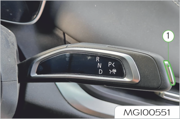
1. P gear button
Shift into P gear
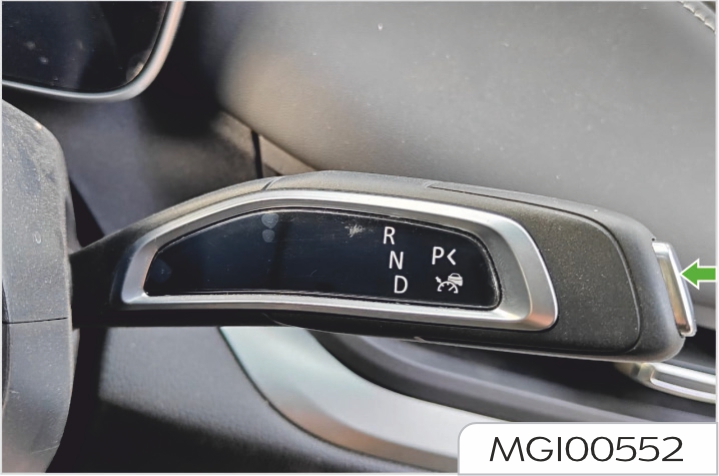
When the vehicle is stationary, press the P gear button (1), and the vehicle engages the P gear
Shift into R, N or D gear
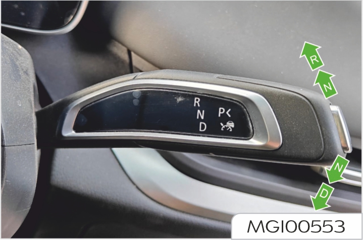
Depress the brake pedal and briefly push or pull the shift lever towards the required direction (two positions each for up and down). After releasing the shift lever, the shift lever will return to the middle position.
Auto Park (automatically return to P gear function)
When the vehicle is started, and the driver leaves the vehicle in D, N or R gear (the movement to open the driver's door to leave the seat), the vehicle will automatically return to P gear to prevent any crack or the risk
of vehicle collision and slipping.
When the the vehicle is powered off, the vehicle will automatically switch to P gear, no matter what gear it is currently in. The vehicle should remain started and N gear should be engaged while the vehicle is in a car wash device to prevent automatic shifting to P gear after the vehicle is powered off.
The type of parking assist system equipped on your vehicle is subject to the actual vehicle configuration purchased.
Camera provides visual aids for the parking assist system. See "Camera" in Driver assistance system for details. Ultrasonic radar provides object detection for the parking assist system.
See "Radar" in Driver assistance system for details.
The parking assist system is not always reliable and is only playing the role of guidance! The parking sensors might not detect some types of obstacles, including slim objects (such as wire nets and ropes), small objects close to the ground, conic objects and some objects with non-reflective surfaces.
The sensors shall be free of dirt, ice, and snow. The sediment on surfaces of sensors will impair the normal functioning of the sensors. Therefore, avoid directly flushing the sensors from a short distance by a high pressure water gun while washing your vehicle.
The sensors installed on the rear bumper are functioned to scan the rearward area of vehicle, in order to judge the presence of obstacles. Upon detection of any obstacle, the parking sensors will calculate its spacing from the rear of the vehicle and send the information to the driver by alerting tones. It's really important that this system is only a parking assist system and can't function as the replacement for your observation and personal judgment.
Working status of parking sensor assist system
After selecting reverse gear, the parking assist system automatically starts working. When selecting other gears, the parking assist system will stop working.
If the system gives out a prompt tone of 3s after the reverse gear is selected, it indicates that the system has a malfunction. Contact Our Service Dealer for service as soon as possible.
Parking process
When the two middle radars in the rear of the vehicle are about 150cm away from the barrier, or when the radars on both sides are about 60cm away from the barrier, the parking assist system starts to make alarm sounds. And the alarm sound become harsher when the vehicle is approaching the barrier.
When the distance of the vehicle from the barrier is less than 30cm, the parking assist system will sound a long alarm. At this moment, it is impossible to effectively identify the barrier if you continue to reverse the vehicle.

The parking assist system is not always reliable and is only playing the role of guidance! The sensors might not detect some types of obstacles, including slim objects (such as wire nets and ropes), small objects close to the ground, conic objects, and some objects with non-reflective surfaces.
The sensors shall be free of dirt, ice, and snow. The sediment on surfaces of sensors will impair the normal functioning of the sensors. Therefore, avoid directly flushing the sensors from a short distance by a high pressure water gun while washing your vehicle.
The radar sensor located in the front bumper will scan the front area of the vehicle, and the radar sensor located in the rear bumper will scan the rear area of the vehicle, in order to judge the presence of obstacles. Upon detection of any obstacle, the parking sensors will calculate its spacing with the vehicle and send the information to the driver by alerting tones. It's really important that this system is only a parking assist system and can't function as the replacement for your observation and personal judgment.
Working status of parking assist system with front and rear sensors
Rear parking assist system
After selecting reverse gear, the parking assist system automatically starts working. After shifting out of the reverse gear, the rear parking assist system stops working.
Front parking assist system
When selecting the reverse gear or the drive gear, the vehicle speed rises from 0km/h to 15km/h, the front parking assist system works; when the vehicle speed drops from 15km/h to 12km/h, the front parking assist system is in standby mode; when the vehicle speed drops to 12km/h or below, the front parking assist system works.
If the system keeps ringing for a long time after the reverse gear or the drive gear is selected, it indicates that the system has a malfunction. Contact Our Service Dealer or service as soon as possible.
Front radar switch on center console screen
Press the front radar switch on center console screen to turn on the front parking assist system.
Parking process
When the two middle radars in the rear of the vehicle are about 150cm away from the barrier, or when the radars on both sides are about 60cm away from the barrier, the parking assist system starts to make alarm sounds. And the alarm sound become harsher when the vehicle is approaching the barrier
When the radars on both sides of the front of vehicle are about 60cm away from the barrier, the parking assist system will start making alarm sounds. And the alarm sound become harsher when the vehicle is approaching the barrier.
When the distance of the vehicle from the barrier is less than 30cm, the parking assist system will sound a long alarm. At this moment, it is impossible to effectively identify the barrier if you continue to reverse the vehicle.
When the distance of the vehicle from the barrier is more than 30cm, the front radar has a mute strategy of 3s with the vehicle in drive gear; if the distance from the barrier does not change after 3s, the alarm sound will stop; if the distance from the barrier changes again, the system will resume sending alarm sound.
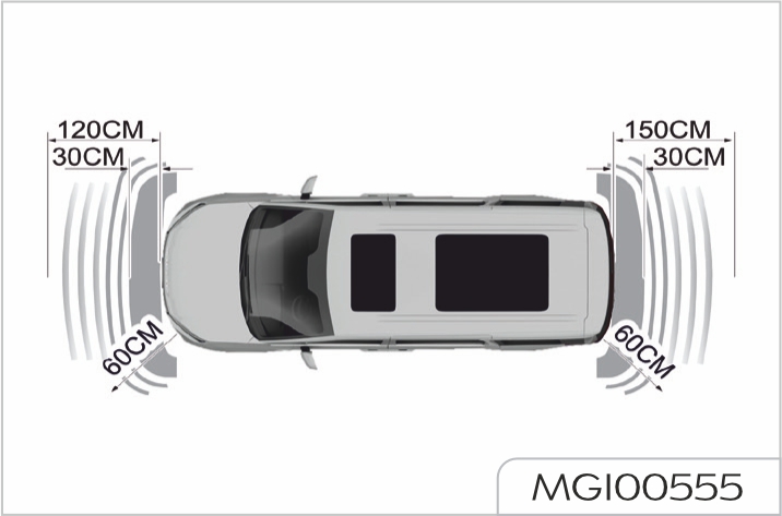
The parking camera assist system is not always reliable and is only playing the role of guidance!
Due to limited visual field, the parking camera can't detect any obstacle beyond its visual field.
Working status of parking camera assist system:
After selecting reverse gear, the image of center console screen will be switched to the working status of parking camera, and the display will show the scene image behind the vehicle for the driver's reference during reversing.
When selecting other gears, the parking camera assist system stops working and the display returns to the original state.
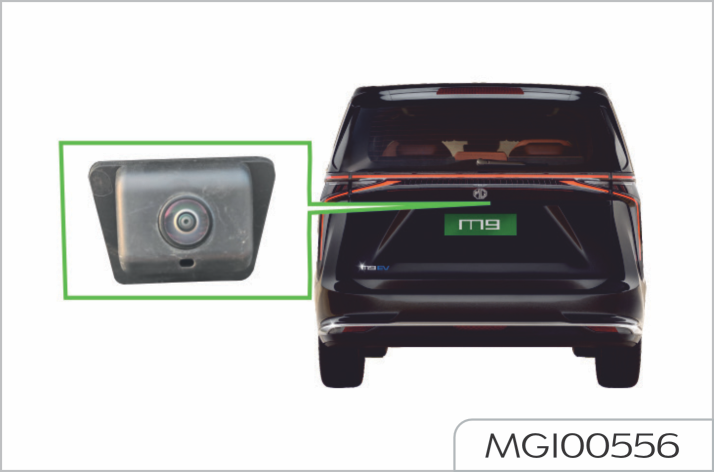
When the vehicle enters the reversing state, cameras will output static reversing tracks which are displayed on the center console screen, take the horizontal plane as reference, and identify the area behind the vehicle in segments divided by red, yellow and green lines.
540° around-view system is not always reliable. It only plays the role of assistance! Due to limited visual field, the camera can't detect any obstacle beyond the blind spot and its visual field; even when the system is running, be also careful to view the environment around the vehicle.
540° around-view system includes four cameras and one controller, and the cameras are respectively located in four orientations of front, rear, left and right.
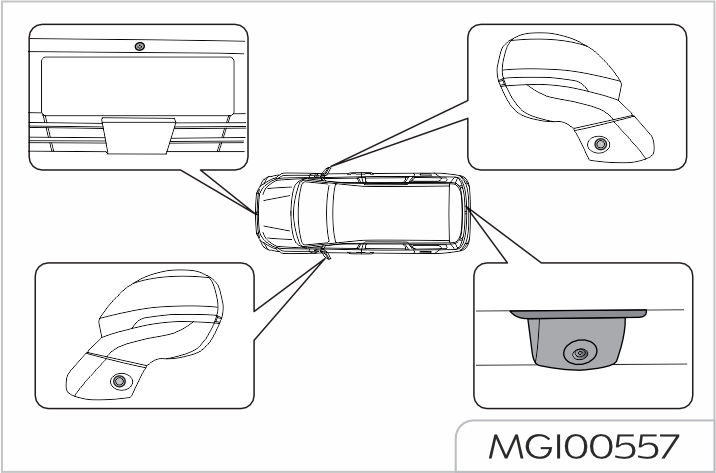
540° around-view system provides multiple auxiliary functions, which mainly include:
The type of 540° around-view system on your vehicle depends on the actual vehicle configuration you purchased.
2D/3D around-view system
Function activation
After the function is activated, 2D/3D and front/rear/left/right viewing angles can be switched in the operation area.
Function deactivation
Function settings
Click the "Settings" on the screen under the panoramic interface, and users can choose to activate/ deactivate the sub-functions such as "steering triggered panorama", "forward trajectory" and "wide viewing angle".
Viewing angle of underbody
The viewing angle of underbody can provide the visual field from underbody, such as observe the manhole cover, curb and tyre returnability
Function activation
Click the "viewing angle of underbody" on the screen under the panoramic interface to enter the interface for viewing angle of underbody, which is front view angle by default.
Function deactivation
The type of advanced driver assistance system on your vehicle depends on the actual vehicle configuration you purchased.
This vehicle is equipped with five types of cameras: surround view camera, smart sideview camera, interior camera, front view camera or front tri-focal camera. The surround view camera provides visual assist for the parking assist system. The interior camera provides object detection for the driver/occupant monitoring system. The smart sideview camera, front view camera or front tri-focal camera provides object detection for the driver assistance system.
Camera mounting location
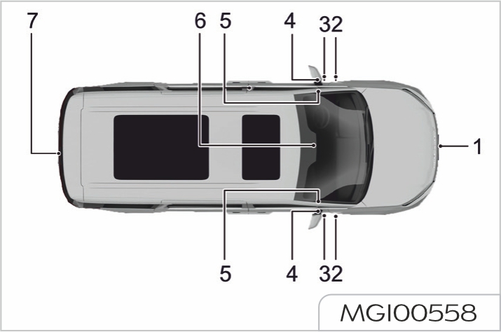
The type and location of cameras on your vehicle depends on your actual vehicle configuration.
When the camora sensor hardware is damaged,must be reapired or replaced timely. It is recommended that you drive your vehicle to Our Service Dealer for repair, instead of replacement by yourself.
No license plate frame and other items are allowed on the front and rear licence plate to prevent interfrence with cameras or radar sensor; the license plate requires regular maintenance and service to prevent their deformation from affecting the performance of rador sensors.
The camers may not work properly in all traffic enviornments, weather and driving conditions. Please deive with care when the driving environments, weather and driving conditions. Please drive care when the driving enviornment is complex or the weather condition is bad.
Camera maintenance
In order to ensure normal operation, please keep the front of the cameras free of foreign matters such as dust, ice, snow, water and frost.
When there are foreign matters in front of the camera, please clean it with a soft cloth. Do not use a high pressure water gun, nor damage the lens of the camera.
The assembled structure after camera replacement must use our original parts. The camera must be re-calibrated at Our Service Dealer after replacement to ensure that all camera-based vehicle systems function properly.
Usage restrictions
When a camera cannot work properly, the functions that rely on the detected information provided by the camera are limited or abnormal.
The detection range and capability of the cameras are limited, and the objects beyond their detection range and capability cannot be detected.
The camera performance will be inhibited in the following environments:
This vehicle is equipped with two types of radar: ultrasonic radar and millimetre wave radar. The ultrasonic radar provides object detection for the parking assist system. The millimetre wave radar provides object detection for the driver assistance system.
Radar mounting location
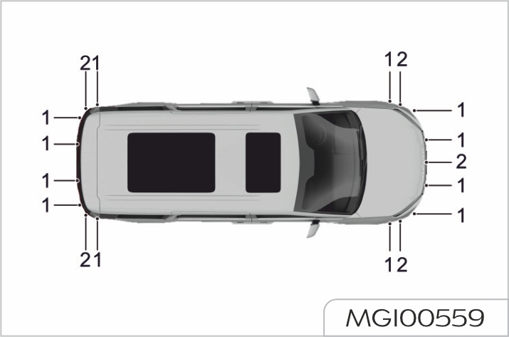
The type and location of radars on your vehicle depends on your actual vehicle configuration.
In order to avoid the influence on the detection performance of radar sensors, it is strictly prohibited to paint or modify the body and front and rear bumpers without permission.
When the radar sensor hardware is damaged, it must be repaired or replaced timely. It is recommended that you drive your vehicle to Our Service Dealer for repair, instead of replacement by yourself
No license plate frame and other items are allowed on the front and rear license plates to prevent interference with cameras or radar sensors; the license plates requires regular maintenance and service to prevent their deformation from affecting the performance of radar sensors.
The radar sensors may not work properly in all traffic environments, weathers, and driving conditions. Please drive with care when the driving environment is complex or the weather condition is bad.
Radar maintenance
In order to ensure normal operation, please keep the front of the radars free of foreign matters such as dust, ice, snow, and water.
When there are foreign matters in front of the radar, please clean it with a soft cloth. Do not use a high pressure water gun, nor damage the front surface of the radar.
The assembled structure after radar sensor replacement must use our original parts. The radar sensor must be re-calibrated at Our Service Dealer after replacement to ensure that all radar sensor-based vehicle systems function properly
Usage restrictions
When a radar cannot work properly, the functions that rely on the detected information provided by the radar are limited or abnormal
The detection range of the radars is limited, and the objects beyond their detection range cannot be detected.
The radar performance will be inhibited in the following environments:
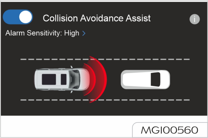
The forward collision assist includes FCW (Forward Collision Warning) and AEB (Automatic Emergency Braking). The forward collision warning function warns the driver of pedestrians, bicycles or vehicles in front of the vehicle with visual and audio signals. If the driver fails to take actions within a reasonable period of time, the system will trigger the automatic emergency braking function.
The collision assist may enable rapid and momentary braking in response to different risks of collision, which may make the driver uncomfortable, and the driver should actively apply brake at this time.
If the risk of collision further increases, the system will brake sharply and stop the vehicle under normal conditions. For most drivers, this is not a normal driving style and they may feel uncomfortable. When the collision assist successfully avoids collision with the vehicle ahead, the vehicle will remain stationary for a short period of time and the driver should take actions as soon as possible.
The driver or occupant usually notices the function of collision assist only when the vehicle is about to collide. The collision assist is activated when the driver should start braking early, but it cannot assist the driver in all cases.
Function activation or deactivation
Function activation method
When the vehicle is started, the collision assist function is activated by default.
To reactivate the function after you deactivate it, set on the center console screen: Settings -> Advanced Driver Assistance -> Activate Collision Assist.
When the function is activated, the
"FCW (Forward Collision Warning)/
AEB (Automatic Emergency Braking)
warning light (yellow)" ![]() on the
instrument cluster is turned off.
on the
instrument cluster is turned off.
Function deactivation method
Set on the center console screen: Settings -> Advanced Driver Assistance -> Deactivate Collision Assist.
When the function is deactivated,
the forward collision warning and
automatic emergency braking will be
turned off at the same time, and the
"FCW (Forward Collision Warning)/
AEB (Automatic Emergency Braking)
warning light (yellow)" ![]() on the
instrument cluster remains on.
on the
instrument cluster remains on.
Sensitivity adjustment
Set on the center console screen by clicking "…" or ">" on the right of Collision Assist to pop up the options "Low", "Standard" and "High"; you can choose the appropriate sensitivity based on your needs.
Information prompts
Visual alarm
- Indicatorprompt: During the
forward collision warning,
the "FCW (Forward Collision
Warning)/AEB (Automatic
Emergency Braking) warning
light (yellow)" ![]() flashes;
during the automatic emergency
braking, the "FCW (Forward
Collision Warning)/AEB
(Automatic Emergency Braking)
warning light (red)"
flashes;
during the automatic emergency
braking, the "FCW (Forward
Collision Warning)/AEB
(Automatic Emergency Braking)
warning light (red)" ![]() flashes.
flashes.
- Text reminder: Risk of collision/ automatic emergency braking.
The collision assist is an auxiliary function that cannot work under all driving, traffic, weather and road conditions, which cannot replace the driving and accurate judgment.
The performance of the system may be degraded by other factors, so that the driver should drive carefully and do not rely solely on the system. Before using the collision assist, the driver should check the restrictions they need to know by referring to this section.
The collision assist is designed to decrease the vehicle speed as much as possible to reduce the losses caused by collisions, instead of complete prevention of collisions. The driver should drive carefully and do not rely on the system.
When the system gives visual and audible warnings, the driver should immediately take further measures to avoid risk of collision and do not rely solely on the system.
The recognition range of front view camera and front millimeter wave radar realized by collision assist is limited, so you should not rely solely on the system to prevent collisions.
Due to the inherent limitations, the system may give a warning or brake when there is no risk of collision. The driver should always pay attention to the traffic environment ahead and take appropriate measures immediately. The operating range of the collision assist system is 8 km/h to 130 km/h.
With the collision assist activated,
if the "FCW (Forward Collision
Warning)/AEB (Automatic
Emergency Braking) warning light
(yellow)" ![]() remains on, please
drive to Our Service Dealer for
service.
remains on, please
drive to Our Service Dealer for
service.
Usage restrictions

The LDW (Lane Departure Warning) function assists the driver on highways, expressways and other similar main roads. When the driver departs from the lane unintentionally, it warns and prompts the driver to return to the current lane, thereby avoiding traffic accident.
The lane departure warning function is activated when the vehicle speed is greater than or equal to 60 km/h and the road markings are clearly visible.
When the vehicle is driven at low speed or actively (judged by turning on the turn signal/rapid lane change, etc.), the system will not give an alarm.
Function activation or deactivation
Function activation method
When the vehicle is started, the lane departure warning function is activated by default.
To reactivate the function after you deactivate it, set on the center console screen: Settings -> Advanced Driver Assistance -> Activate Lane Keeping Assist.
Function deactivation method
Set on the center console screen: Settings -> Advanced Driver Assistance -> Deactivate Lane Keeping Assist.
When the function is deactivated, the
"LDW (Lane Departure Warning)/
LKA (Lane Keeping Assist)/ELK
(Emergency Lane Keeping) warning
light (yellow)"
![]() on the instrument
cluster remains on.
on the instrument
cluster remains on.
Sensitivity adjustment
Set on the center console screen by clicking "…" or ">" on the right of Lane Keeping Assist to pop up the options "Low", "Standard" and "High"; you can choose the appropriate sensitivity based on your needs.
Information prompts
When the driver departs from the lane unintentionally, the system will remind the driver through the warning icon on the instrument cluster, accompanied by the sound of the buzzer, and the lane line on the corresponding side on the instrument cluster is displayed in red. This means that the vehicle is at risk of departing from the lane. In this case, the driver should correct the vehicle to return to the current lane immediately.
The lane departure warning is only an alarm-assisted driving function.
The driver should not rely solely on the lane departure warning function to remind the departure, and should bear the responsibility for safe driving.
The lane departure warning cannot work under all driving or traffic, weather and road conditions.
When the lane keeping assist
system fails, i.e. after the lane
keeping assist function is activated,
the "LDW (Lane Departure
Warning)/LKA (Lane Keeping
Assist)/ELK (Emergency Lane
Keeping) warning light (yellow)"
![]() remains on, please drive to
Our Service Dealer for service.
remains on, please drive to
Our Service Dealer for service.
Usage restrictions
The lane departure warning cannot clearly detect lane lines at all times. You may receive useless or invalid warning under the following conditions:
- See "Camera" for camera restrictions.
- Weather conditions (heavy rain, snow, fog, extremely high or low temperatures) interfere with camera operation.
The above warnings and restrictions do not include all conditions that may interfere with lane departure warning. Many factors may cause the lane departure warning to be inoperative. In order to avoid departure, the driver should remain vigilant and always pay attention to the road conditions, so that corrective measures are taken as soon as possible.
When the LKA (Lane Keeping Assist) function is activated, it determines the position of the vehicle relative to the lane lines based on the road boundary information obtained by the cameras, and shall warn the driver or return the vehicle to the lane by steering intervention in combination with the vehicle status and driver input if the driver departs from the lane unintentionally. This is a safety function that only corrects the deviation when the vehicle is about to deviate from the lane, not a comfort function of lane centering type, so the driver should firmly hold the steering wheel at all times during use.
The lane keeping function is activated when the vehicle speed is between 60 km/h and 120 km/h and the road markings are clearly visible.
When the vehicle is driven at low speed or actively (judged by turning on the turn signal/rapid lane change, etc.), the system will not give an alarm or automatically intervenes in steering.
Function activation or deactivation
The LKA (Lane Keeping Assist) shares the switch of LDW (Lane Departure Warning), and its specific operations are shown in "LDW (Lane Departure Warning)" in this section.
Information prompts
When the driver departs from the lane unintentionally, the system will remind the driver through the warning icon on the instrument cluster and the sound
of the buzzer, and may intervene in steering to return the vehicle to the current lane.
The lane keeping assist is just a driver assistance function.
The driver should not rely solely on the lane keeping assist function to prevent departure from the lane, and should bear the responsibility for safe driving. The driver should follow the traffic regulations and hold the steering wheel firmly with both hands. If the driver does not hold the steering wheel, the system will not provide the keeping assist function.
The lane keeping assist will not always help the driver to correct the vehicle with a tendency of departure, and the driver must take over the vehicle after correction to ensure that the vehicle is stable. The lane keeping assist cannot work under all driving or traffic, weather and road conditions.
When the lane keeping assist
system fails, i.e. after the lane
keeping assist function is activated,
the "LDW (Lane Departure
Warning)/LKA (Lane Keeping
Assist)/ELK (Emergency Lane
Keeping) warning light (yellow)"
![]() remains on, please drive to
Our Service Dealer for service.
remains on, please drive to
Our Service Dealer for service.
If the vehicle suspension kit replaced by yourself is not approved by us, the lane keeping assist system may not operate properly
Usage restrictions
The lane keeping assist cannot clearly detect lane lines at all times. You may receive invalid warning or false interference under the following conditions.
-See "Camera" for camera restrictions.
-Weather conditions (heavy rain, snow, fog, extremely high or low temperatures) interfere with camera operation.
The above warnings and restrictions do not include all conditions that may interfere with lane keeping assist. Many factors may cause the lane keeping assist to be inoperative. In order to avoid departure, the driver
should remain vigilant and always pay attention to the road conditions, so that corrective measures are taken as soon as possible.
When the ELK (Emergency Lane Keeping) function is activated, it determines the position of the vehicle relative to the adjacent vehicle or curb, etc. based on the road environment information obtained by the front cameras and corner millimeter wave radars, and will warn the driver or keep the vehicle away from the risk of collision by steering intervention in combination with the vehicle status and driver input if the driver departs unintentionally, causing risk of collision with the adjacent vehicle or curb, etc. This is a safety function, not a comfort function.
The lane keeping function is activated when the vehicle speed is between 60 km/h and 120 km/h and the road markings are clearly visible.
When the vehicle is driven at low speed or actively (judged by rapid lane change, etc.), the system will not give an alarm or automatically intervenes in steering.
Function activation or deactivation
The ELK (Emergency Lane Keeping) shares the switch of LDW (Lane Departure Warning), and its specific operations are shown in "LDW (Lane Departure Warning)" in this section.
Information prompts
When the driver departs unintentionally and there is a risk of collision with the adjacent vehicle or curb, etc., the system will remind the driver through the warning icon on the instrument cluster and the sound of the buzzer, and may intervene in steering to keep the vehicle away from the adjacent vehicle or curb, etc. to avoid the risk of collision.
The emergency lane keeping assist is just a driver assistance function. The driver should not rely solely on the emergency lane keeping function to prevent collision with the adjacent vehicle or curb, and should bear the responsibility for safe driving.
The driver should follow the traffic regulations and hold the steering wheel firmly with both hands. If the driver does not hold the steering wheel, the system will not provide the emergency keeping assist function.
The emergency lane keeping assist will not always help the driver correct the vehicle with a tendency to collide with the adjacent vehicle or curb, and the driver must take over the vehicle after correction to ensure that the vehicle is stable.
The emergency lane keeping assist cannot work under all driving or traffic, weather and road conditions.
When the emergency lane keeping
assist system fails, i.e. after the lane
keeping assist function is activated,
the "LDW (Lane Departure
Warning)/LKA (Lane Keeping
Assist)/ELK (Emergency Lane
Keeping) warning light (yellow)"
![]() remains on, please drive to
Our Service Dealer for service.
remains on, please drive to
Our Service Dealer for service.
If the vehicle suspension kit replaced by yourself is not approved by us, the emergency lane keeping assist system may not operate properly.
Usage restrictions
The emergency lane keeping assist cannot clearly detect lane lines at all times. You may receive invalid warning or false interference under the following conditions.
-See "Camera" for camera restrictions.
-Weather conditions (heavy rain, snow, fog, extremely high or low temperatures) interfere with camera operation.
The above warnings and restrictions do not include all conditions that may interfere with emergency lane keeping assist. Many factors may cause the emergency lane keeping assist to be inoperative. In order to avoid the risk of collision with the adjacent vehicle or curb, the driver should remain vigilant and always pay attention to the road conditions, so that corrective measures are taken as soon as possible.
ACC (Adaptive Cruise Control) can help the driver maintain the same speed as the vehicle ahead for the preselected time interval. The adaptive cruise control system can bring you a more relaxed and comfortable driving experience when driving on smooth expressways and long straight roads. The driver can set the required vehicle speed and the time interval with the front vehicle. When the camera and front millimeter wave radar sensor detect that the vehicle ahead is slowing down, your vehicle will automatically slow down accordingly. When the road ahead is clear again, your vehicle will be restored to the selected speed.
Adaptive cruise control switch
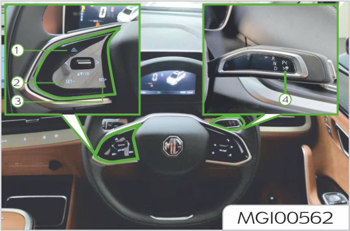
The adaptive cruise control switches are located on the steering wheel and shift lever.
Activation of adaptive cruise control
When an object is detected ahead after the vehicle is started, the cruise control function can be activated at any speed; if no object is detected ahead, the vehicle speed should be kept above 15 km/h before you can activate the cruise control function.
When the "ACC (Adaptive Cruise
Control) indicator (gray)
![]() on the
instrument cluster illuminates, you
can use the adaptive cruise control
function, which is in standby state.
In this state, you can move the shift
lever down to the bottom and release
it to activate the ACC (Adaptive Cruise
Control) function.
on the
instrument cluster illuminates, you
can use the adaptive cruise control
function, which is in standby state.
In this state, you can move the shift
lever down to the bottom and release
it to activate the ACC (Adaptive Cruise
Control) function.
When the ACC (Adaptive Cruise
Control) function is activated, the "ACC
(Adaptive Cruise Control) indicator
(blue)
![]() the instrument cluster
illuminates.
the instrument cluster
illuminates.
After the system is activated, the vehicle will cruise at the set cruise speed when there is no vehicle ahead; when there is a target vehicle ahead, and its speed is greater than the set cruise speed of the vehicle, the system will allow the vehicle to continue driving at the current cruise speed; when its speed is less than the set
cruise speed of the vehicle, the system will actively adjusts the speed to maintain the set following time interval from the vehicle ahead to achieve automatic following.
When the vehicle ahead accelerates, the system will also actively accelerate until the set cruise speed is restored.
The ACC (Adaptive Cruise Control) will intelligently limit the speed on curves.
Adjustment of cruise speed
When the ACC (Adaptive Cruise Control) is activated, the cruise speed can be increased or decreased through RES+ and SET-. Short press RES+/SET- to change the cruise speed by 5 km/h. Long press RES+/SET- to change the cruise speed by 1 km/h. With the ACC (Adaptive Cruise Control) in the override state, press the SETbutton to synchronize the speed, i.e. the cruise speed becomes the current actual speed.
Cruise speed memory
To use the previous cruise speed when activating the cruise control, move the shift lever down to the bottom for more than 1 second, and then release it.
Adjustment of cruise distance
Short press the to switch the following distance from Level 1 to Level 3 cyclically for each press, and the current cruise distance can be confirmed through the display on the instrument cluster.
Deactivation of adaptive cruise control
To manually deactivate the cruise control, pull up the shift lever or shift the gear, and depress the brake pedal. When the cruise control is deactivated, the ACC (Adaptive Cruise Control) indicator will change from blue to gray, or the ACC (Adaptive Cruise Control) indicator will go out.
Restoration of adaptive cruise control
To use the previous cruise speed when activating the cruise control, move the shift lever down to the bottom for more than 1 second, and then release it.
When cruising at the current speed, the adaptive cruise control can be restored by activating it.
The system will enter the function hold state and will not be restored under the following conditions, and the instrument cluster will provide the relevant information to indicate the need to restore cruise control:
The driver must always pay attention to the current traffic conditions and intervene when the adaptive cruise control system fails to maintain a proper speed or a correct distance. The adaptive cruise control system is unable to deal with all traffic, weather and road conditions.
The ACC is not a safety system, obstacle detector or collision warning system, but a comfort system. The driver must maintain control of the vehicle at all times and take full responsibility for the vehicle.
The function of ACC can assist the driver, but cannot replace the driver in driving. The driver must drive carefully and follow the speed limit regulations even when the ACC is activated.
When driving uphill or downhill, due to system limitations, there may be a certain error between the actual cruise speed of the ACC and the set cruise speed. Sufficient speed control may not be provided due to limited braking capacity and driving on a slope, and the distance to the vehicle ahead may be misjudged.
Usage restrictions
The adaptive cruise control relies on other systems, such as ESP system. If the function of any system is disabled, the adaptive cruise control system will be automatically disabled. In the case of automatic deactivation, a sound signal will be emitted and a message will be displayed on the driver side display. The driver must intervene to match the speed and distance of the vehicle ahead. The causes of automatic disabling may be:
The ICA (Integrated Cruise Assist) is used to assist the driver in operating the vehicle on a structured road, and reduce the driver's fatigue due to repeated driving behavior during long-distance driving. This function can provide longitudinal and transverse auxiliary controls of the vehicle according to the traffic conditions in the driving direction; longitudinal control can achieve cruise control and car following, while transverse control enables the vehicle to be controlled near the center of lane according to the lane lines on both left and right, providing the driver with an easier driving mode.
The integrated cruise assist aims to follow the vehicle ahead and maintain the vehicle in its own lane at the following time interval set by the driver. If the camera and front millimeter wave radar sensor cannot detect any vehicle ahead, the speed set by the driver will be maintained. The above situation also occurs if the speed of the vehicle ahead exceeds the set speed. If the camera cannot see the lane lines ahead, the integrated cruise assist function will be restricted and degraded to adaptive cruise control.
Activation of integrated cruise assist
When the "ICA (Integrated Cruise
Assist) indicator (gray)"
![]() on the
instrument cluster illuminates, you can
use the ICA (Integrated Cruise Assist)
function, which is in standby state.
In this state, you can move the shift
lever down to the bottom twice
continuously and release it to activate
the ICA (Integrated Cruise Assist)
function.
on the
instrument cluster illuminates, you can
use the ICA (Integrated Cruise Assist)
function, which is in standby state.
In this state, you can move the shift
lever down to the bottom twice
continuously and release it to activate
the ICA (Integrated Cruise Assist)
function.
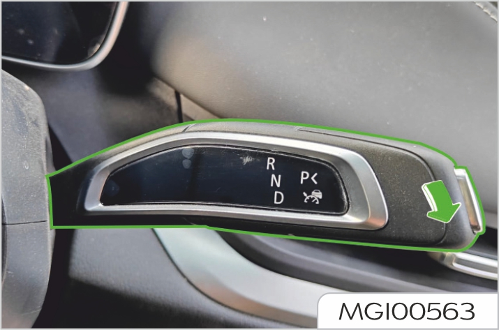
When the ICA (Integrated Cruise
Assist) function is activated, the "ICA
(Integrated Cruise Assist) indicator
(blue)"
![]() on the instrument cluster
illuminates.
on the instrument cluster
illuminates.
Deactivation of integrated cruise assist
To manually deactivate the cruise control, pull up the shift lever or shift the gear, and depress the brake pedal. When the cruise control is deactivated, the ICA (Integrated Cruise Assist) indicator will change from blue to gray, or the ACC (Adaptive Cruise Control) indicator will go out.
Restoration of integrated cruise assist
Recover by shifting the shift lever down to the bottom twice.

The integrated cruise assist is not a collision avoidance system. If the system does not detect the vehicle ahead, the driver must intervene. For intersections, the integrated cruise assist may correct the steering wheel, and require the driver to hold the steering wheel at the intersections and get ready to take over the vehicle at any time.
For people or animals, as well as small vehicles such as bicycles, motorcycles and electric bicycles, the integrated cruise assist will not apply the brake. This is also the case for flatbed trailers and approaching, slowly moving or stationary vehicles and objects.
The integrated cruise assist shall not be used in case of urban roads, intersections, slippery surfaces, roads with accumulated water or mud, cloudy, rainy or snowy weather, poor visibility, winding roads or highway entrances and exits.
The driver assistance system is not suitable for the situation in which sunlight obliquely shines on the camera from the front of the vehicle and the case in which the high beam coming from the opposite side shines on the camera at night when entering/leaving the tunnel entrance.
The integrated cruise assist may be deactivated when the direction of lane lines ahead changes rapidly, such as lane merge, road diversion, sudden increase or decrease in lane width, please always take over the vehicle in advance.
The integrated cruise assist will occasionally assist the vehicle in steering when the steering assist is not required or when you do not intend to steer, which may be due to unclear or irregular lane lines, or other lines or objects similar to the lane lines on the lane surface. In this case, the driver should take over the vehicle immediately.
When the integrated cruise assist system detects that the driver does not hold the steering wheel, it will provide a takeover request prompt "Please turn the steering wheel slightly" through the instrument cluster, and give an audible alarm, accompanied by flashing of a white light band. At this time, the driver should hold the steering wheel immediately and take over the steering wheel if necessary to avoid danger.
If the system detects that you have not taken over the vehicle for multiple times, the function will automatically exit to ensure driving safety.
If the driver ignores the alarm message for several consecutive times in a driving cycle, the ICA (Integrated Cruise Assist) function can no longer be used. The vehicle may not use the ICA (Integrated Cruise Assist) function until the next ignition cycle.
Usage restrictions
The causes of automatic disabling may be:
- If the vehicle ahead is braked suddenly, unexpected braking or failure to brake may occur due to the restrictions of the camera and front millimeter wave radar. If the vehicle ahead is braked suddenly, unexpected braking or failure to brake may occur due to the restrictions of the camera and front millimeter wave radar.
- The integrated cruise assist is mainly used when driving on flat roads with clear lane lines. When driving with heavy loads on steep downhill roads, it may be difficult for the function to maintain the correct distance from the vehicle ahead. In these cases, be careful and prepare to brake at any time.
- When driving on roads with sharp turns, such as on a serpentine road, the integrated cruise assist function may not detect the vehicle ahead due to the limited view of the front millimeter wave radar sensor and camera, which may cause the integrated cruise assist to accelerate the vehicle, and the driver should be ready to take over the vehicle at any time.
- If the distance between the vehicle with integrated cruise assist and the adjacent lane is too small (or the vehicle in the adjacent lane is too close to the vehicle with integrated cruise assist), the integrated cruise assist may respond to the vehicle and brake, and the driver should pay attention to the road changes and take over the vehicle immediately.
- The performance of integrated cruise assist on a slope depends on the vehicle speed, load, and gradient. When the vehicle runs uphill, it may be required to depress the accelerator pedal to maintain the vehicle speed. When the vehicle runs downhill, it may be required to brake or shift to a low gear to maintain the vehicle speed.
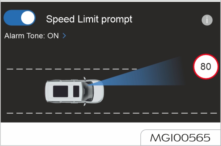
The SLIF (Speed Limit Information Function) recognizes speed signs by using the intelligent front view camera and sends relevant information to the instrument cluster to remind the driver of the speed limit information of the current road and prevent overspeed. The system does not actively adjust the vehicle speed at this time, and the driver should actively control the vehicle speed.
Function activation or deactivation
Set on the center console screen: Settings -> Advanced Driver Assistance -> Speed Limit Assist, where you can activate/deactivate the speed limit information function.
Function activation conditions
After the function is activated, it will not work temporarily when the vehicle speed is greater than 130 km/h.
Information prompts
If a speed limit sign is recognized when the current vehicle speed is less than the speed of the speed limit sign after the function is activated, the instrument cluster will display the current speed limit value.
If it is detected that the current vehicle speed is greater than the speed of the speed limit sign, the speed limit sign will flash with an audible alarm.
![]() indicates the speed limit value of
the current road.
indicates the speed limit value of
the current road.
When the system cannot recognize the information of the speed limit sign ahead, the instrument cluster will not display the speed limit sign information.
The system only displays the speed limit information, and does not control the vehicle speed.
The recognition of speed limit signs by the system is not entirely accurate, so that false recognition may occur, and the driver should drive carefully according to the actual road conditions.
Usage restrictions
The traffic sign information function works properly only when the speed signs are clearly visible. It may not work properly or may not work in some cases. For example:
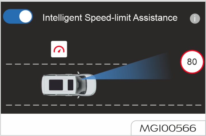
The ISA (Intelligent Speed Assistance) recognizes the speed signs by using the intelligent front view camera when the ACC function is activated, and sends relevant information to the instrument cluster to remind the driver to decelerate. If the driver fails to decelerate immediately, the system will actively decelerate.
When the intelligent speed assistance function is active, the system will actively decelerate according to the information of the speed limit sign. If the driver requires acceleration subjectively, the vehicle speed can be controlled by depressing the accelerator pedal. When the driver releases the accelerator pedal, the system will restore the speed limit control. The system will also deactivate the speed limit control by short pressing or long pressing the RES+ button.
Function activation or deactivation
Set on the center console screen: Settings -> Advanced Driver Assistance -> Speed Limit Assist, where you can activate/deactivate the speed limit information function.
Function activation conditions
After the function is activated, it will not work temporarily when the vehicle speed is less than 25 km/h or greater than 130 km/h.
Information prompts
If a speed limit sign is recognized
when the current vehicle speed is
less than the speed of the speed limit
sign after the function is activated,
the instrument cluster will display the
current speed limit value
![]() .
.
If it is detected that the current vehicle
speed is greater than the speed of
the speed limit sign, the system will
actively decelerate, the intelligent
speed assistance function will be
activated, the speed limit sign will
flash, and the instrument cluster will
display
![]() .
.
When the system cannot recognize the information of the speed limit sign ahead, the instrument cluster will not display the speed limit sign information.
The recognition of speed limit signs by the system is not entirely accurate, so that false recognition may occur, and the driver should drive carefully according to the actual road conditions.
This is an auxiliary function only and cannot help the driver decelerate at any time. The driver should always pay attention to the traffic ahead and follow the traffic regulations.
Usage restrictions
The traffic sign information function works properly only when the speed signs are clearly visible. It may not work properly or may not work in some cases. For example:
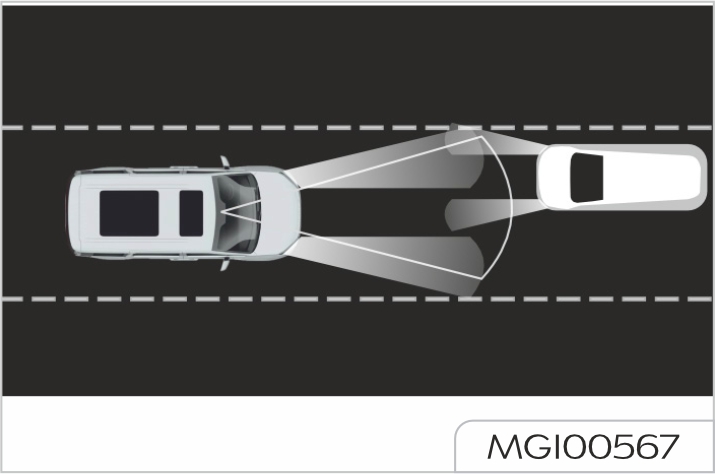
The IHC (Intelligent Headlight Control) recognizes the traffic environment ahead through the front view camera on the vehicle, and automatically controls the switching of high and low beams to prevent dazzling the vehicle ahead and oncoming vehicles, and improve the driving safety and comfort in dark environments, especially at night.
Function activation or deactivation
Function activation method
Set on the center console screen: Exterior Lights -> Light Settings -> Activate Intelligent Headlight Control Switch.
Function deactivation method
The intelligent headlight control can be deactivated in two ways:

Function activation conditions
After the function is activated, it will not work temporarily when the vehicle speed is less than 25 km/h.
Information prompts
When the intelligent headlight control function is activated, its operation can be observed through the auto high beam indicator on the instrument cluster.
When the "IHC (Intelligent Headlight
Control) indicator (blue)"
![]() illuminates, the conditions for turning
on the high beam are met currently,
and the system automatically turns on
the high beam.
illuminates, the conditions for turning
on the high beam are met currently,
and the system automatically turns on
the high beam.
When the "IHC (Intelligent Headlight
Control) indicator (gray)"
![]() illuminates, the conditions for
turning on the high beam are not
met currently, and the system
automatically turns off the high beam.
illuminates, the conditions for
turning on the high beam are not
met currently, and the system
automatically turns off the high beam.
When the intelligent headlight control function fails, the instrument cluster will prompt that the system is unavailable through the pop-up box "Intelligent headlight control unavailable".
The front view camera module is mounted on the windshield, which shall not be blocked, otherwise the function will be inhibited.
The perception of surrounding environment by the intelligent headlight control function is not entirely accurate, which may cause false adjustment of high beam/low beam. Please follow the local traffic regulations and use this function in a compliant and reasonable manner.
The intelligent headlight control is a comfort function only, and the driver should also drive carefully when using it.
Usage restrictions
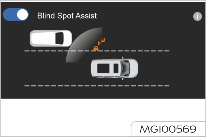
The blind spot assist includes two active safety assist functions:
BSD (Blind Spot Detection) and LCA (Lane Change Assist). When the subsystem detects that a vehicle is approaching at higher speed in the blind spot of rearview mirrors or from a distance, the system will warn the driver through the LED lights on the left and right exterior rearview mirrors.
Function activation or deactivation
Set on the center console screen: Settings -> Advanced Driver Assistance -> Blind Spot Assist, where you can activate/deactivate the blind spot assist function. If the switch is grayed out and cannot be operated, please drive to Our Service Dealer for service.
Detection diagram
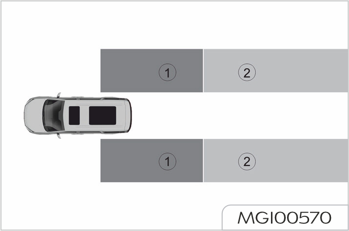
Area 1 is about 3 m behind the vehicle blind spot; area 2 is about 70 m behind the vehicle blind spot.
Blind spot refers to the blind areas behind the left and right rearview mirrors of the vehicle (as shown in Area 1). If there is a vehicle in this area, this function will provide the driver with a favorable prompt to avoid the risk of collision caused by turning or lane change.
If there is a vehicle driven at high speed (much higher than that of the vehicle) as shown in Area 2, this function will provide the driver with a favorable prompt to avoid the risk of collision caused by turning or lane change.
Warning and prompt
When the vehicle is driven at a speed of more than 15 km/h, and there is a vehicle in the area 1 or a vehicle is approaching quickly in the area 2, the system will actively prompt the driver, and the indicator on the corresponding side will illuminate, as shown in the figure below.
If the driver intends to change lanes or turn (turn on the turn signal on the side with a vehicle) at this time, the indicator on the corresponding side flashes to warn the driver.
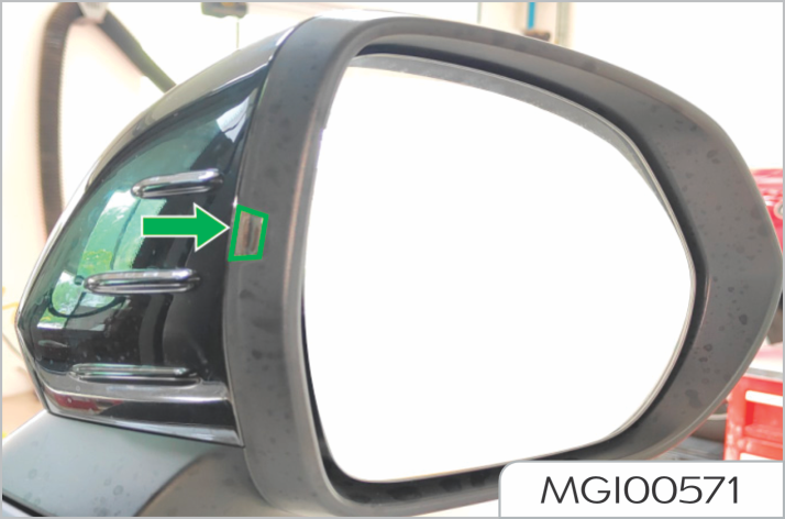
In case of sharp turns, the blind spot detection and lane change assist will not provide warning assistance.
The blind spot assist is a driver assistance function, which cannot provide assistance in all situations.
The blind spot assist is to provide better auxiliary functions in conjunction with the left and right rearview mirrors, and cannot replace the rear observation function of rearview mirrors.
If the indicator of exterior rearview mirror remains on, lease drive to Our Service Dealer for service.
Usage restrictions
The RCTA (Rear Cross Traffic Alert) is a driver assistance function, which warns the vehicles or pedestrians crossing on both left and right sides when the driver reverses the vehicle; the speed range of the rear cross traffic alert function is between 0 and 10 km/h.
Function activation or deactivation
Set on the center console screen: Settings -> Advanced Driver Assistance -> Blind Spot Assist, where you can activate/deactivate the blind spot assist function.
If the switch is grayed out and cannot be operated, please drive to Our Service Dealer for service.
Detection diagram

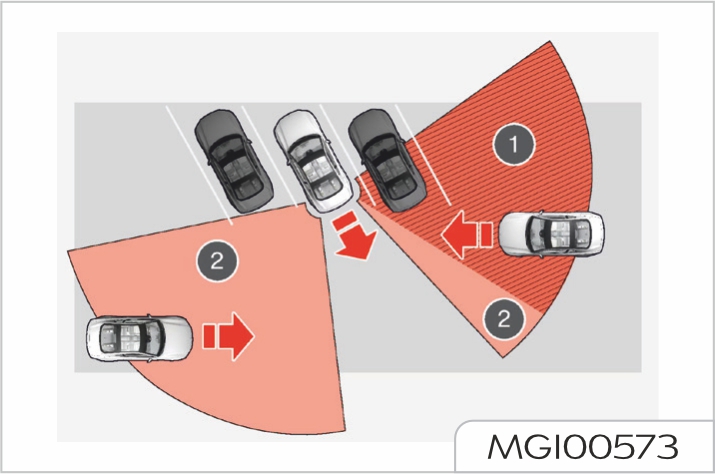
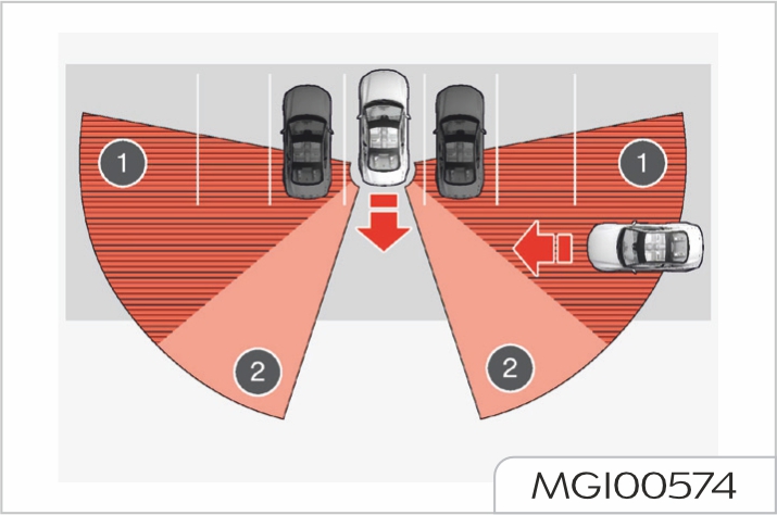
Warning and prompt
When the vehicle is in reverse mode (R gear), and there
are vehicles and pedestrians crossing on both sides behind the vehicle, the indicator on the rearview mirror on the corresponding side will remind the driver by flashing, accompanied by alarm tone.
The rear cross traffic alert cannot replace the rear observation function of rearview mirrors.
The rear cross traffic alert is a driver assistance function, which cannot provide assistance in all situations.
The rear cross traffic alert does not mean that the driver may relax, and it is the driver's responsibility to reverse in a safe manner.
Usage restrictions
When the vehicle is stationary and in a gear other than R, the door opening warning function can detect objects such as vehicles, cyclists or pedestrians approaching from behind. If the driver or occupant opens the door when an approaching object is detected, the door opening warning will give a warning prompt, so that the driver or occupant avoids the risk of scratching with the object.
Function activation or deactivation
Set on the center console screen: Settings -> Advanced Driver Assistance -> Blind Spot Assist, where you can activate/deactivate the blind spot assist function.
If the switch is grayed out and cannot be operated, please drive to Our Service Dealer for service.
Detection diagram
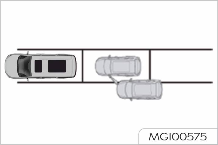
Warning and prompt
When an object is approaching the stationary vehicle, the door opening warning function will illuminate the
warning indicator. In this case, the driver or occupant should not open the door, but confirm the safety of door opening first.
If the driver or occupant opens the door on the alarm side at this time, the warning indicator will flash, while the corresponding pop-up window and alarm tone are also provided on the instrument cluster, and the door atmosphere light on the corresponding side will illuminate to remind the driver or occupant to pay attention to the safety of door opening.
The door opening warning function is a driver assistance function, which cannot work in all situations and replace the rear observation function of rearview mirrors. The door opening warning function is limited by the principles of the sensor and complexity of traffic environment, and may give unnecessary or missed alarms. Active observation of the door opening environment before exit is the most effective measure for the driver and occupant to ensure personal safety
Usage restrictions
The above warnings and restrictions do not include all conditions that may interfere with Door Opening Warning (DOW). In order to avoid scratches when opening a door, the driver and occupant should check if the door opening environment is safe and suitable.
It applies to vehicles configured with driver monitoring system (DMS).
The DMS provides the functions of driver fatigue detection, driver distraction detection, driver smoking behaviour detection and driver phone use behaviour detection for the driver through the cameras in the vehicle and at the inner side of A pillar as well as the "Algorithms for human face and fatigue" built in the entertainment mainframe.
Enter Settings -> Click on the driver status monitoring switch , which can control the alarm display of all functions as a whole, and can meanwhile individually control the prompts for various functional alarms.
Driver fatigue detection
When the driver is fatigued to some extent, the DMS will estimate the fatigue degree of the driver through common fatigue behaviours such as yawning, eyes closing, etc., and conclude the fatigue degree of the driver through estimated results. If the fatigue degree exceeds a certain standard, the DMS will remind the
driver through pop-up window and alarm on the instrument pack. To ensure driving safety, when the driver has fatigue behaviours, the DMS will actively activate the functions of collision assist and lane assist and adjust the sensitivity of the corresponding function. When turning off the switch for driver fatigue monitoring, only instrument pop ups and alarms will be turned off.
This function will work with the vehicle speed not less than 10km/h, and distinguish mild fatigue, moderate fatigue and severe fatigue.
Driver distraction detection
When the driver gazes around during normal driving, the DMS will assess the overall focus direction of the driver according to the overall angle and time of head rotation or the direction and time of line of sight deviation of the driver, so as to judge the driver's distraction behaviour. The system will remind the driver through instrument panel pop-up windows and alarm sounds.
It should be noted that, due to existence of time assessment, observing rearview mirrors and onboard mainframe for a short period of time will not trigger the distraction detection. To ensure driving safety, when the driver has distraction behaviours, the DMS will actively activate the function of collision assist and adjust the sensitivity of the corresponding function. When the switch for driver distraction monitoring is turned off, only the instrument pop-up window and alarm will be turned off.
In addition, this function will be temporarily turned off to avoid misjudgment when it's required to call the body camera to project the scenarios to the on-board mainframe under circumstances like reversing. This function will work with the vehicle speed not less than 10km/h.
Driver smoking behaviour detection
When the DMS detects the smoking behaviour of the driver during driving, the driver will be reminded through pop-up window and alarm on the instrument pack. This function will work with the vehicle speed not less than 10km/h. When the switch for monitoring driver smoking behaviour is turned off, only the instrument popup window and alarm will be turned off.
Driver phone use behaviour detection
When the DMS detects that the driver answers the phone with a hand during driving, the driver will be reminded through pop-up window and alarm on the instrument pack. This function will work with the vehicle speed not less than 10km/h. When the switch for monitoring the driver's phone behaviour is turned off, only the instrument pop-up window and alarm will be turned off.
The exterior rearview mirror glasses are convex shaped to broaden the field of view: this makes objects appear smaller and further away than they really are.
Always check all rearview mirrors for cleanliness and positioning before driving; clean and adjust if necessary.
Power exterior rearview mirrors
Press the left (L) or right (R) switch (Figure 1) to select the exterior rearview mirror on the corresponding side. At the same time, the indicator near the L/R on the selected switch illuminates.
Press four arrows on the round switch (Figure 2), to adjust the angle of exterior rearview mirror.
Press the L or R switch (Figure 1) again, the corresponding indicator goes out, and the adjustment of mirror can be stopped to prevent accidentally modification of adjusted mirror angle.
Switches of exterior rearview mirror not equipped with power folding function.
Folding of exterior rearview mirrors
Manual folding of exterior rearview mirrors
To protect the safety of pedestrians, the outside rear view mirrors will rotate to two sides from the normal installation position when suffering a strong impact. Reset the exterior rearview mirrors by applying little pressure onto the mirror frames.
Power folding exterior rearview mirrors
For vehicles equipped with power folding exterior rearview mirrors, it is allowed to fold/unfold exterior rearview mirrors manually/ automatically
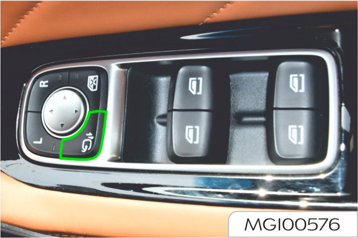
When the exterior rearview mirrors are unfolded, the vehicle power supply is turned off, and all doors and front compartment hood are closed, the exterior rearview mirrors will be automatically folded after the vehicle is locked.
The function setting of automatic/ power folding exterior rearview mirrors can be conducted through the touch button on the center console screen.
Both the mirror power adjustment and the power folding of exterior rearview mirrors are operated by power switch, directly operating with hands may cause failures of relevant devices, and directly injecting the high-pressure water column will cause failures of electric device when washing the vehicle.
Heated exterior rearview mirrors
For vehicles with heated exterior rearview mirrors, the exterior rearview mirrors are integrated with heating element, to remove the frost
or fog on the mirror. The heating
function of mirror is enabled together
the rear window heating operation,
that is to say, only after the power
system is started, when the rear
defrost button is enabled
![]() , the
heating function of exterior rearview
mirrors can function at the same time.
Memory function of exterior rearview
mirrors For vehicles with memory
function of exterior rearview mirrors,
the memory function of exterior
rearview mirrors has 3 gears, bound
with the seat memory function; enter
the seat interface on the center
console screen, to select the driver
memory touch button, and adjust the
exterior rearview mirrors according
to the prompts. Short press the gear
switch to select the position of exterior
rearview mirrors at this gear.
, the
heating function of exterior rearview
mirrors can function at the same time.
Memory function of exterior rearview
mirrors For vehicles with memory
function of exterior rearview mirrors,
the memory function of exterior
rearview mirrors has 3 gears, bound
with the seat memory function; enter
the seat interface on the center
console screen, to select the driver
memory touch button, and adjust the
exterior rearview mirrors according
to the prompts. Short press the gear
switch to select the position of exterior
rearview mirrors at this gear.
Exterior rearview mirror ‘tilt down in reverse’ function
For models equipped with the exterior rearview mirror memory function, the exterior rearview mirror ‘tilt down in reverse’ function operates as follows:
The next time when the vehicle is shifted into Reverse gear, the mirrors will recall the position memorized during the last reverse, and shifting out of Reverse gear will restore their normal driving positions. If readjustment is required, it can be done again by following the above steps.
You can set the ‘tilt down in reverse’ settings of Left Side Only, Right Side Only, and Both Sides on the central screen, please choose according to your driving habits.
Adjust the interior rearview mirrors, to obtain possible optimum viewing angle. The anti-dazzle function of interior rearview mirrors can reduce the dazzling effect of vehicle headlights behind at night.
Manual anti-dazzle interior rearview mirrors
Move the adjusting handle at the bottom of interior rearview mirrors, to change the viewing angle of rearview mirrors, achieving the anti-dazzle function. Push the adjusting handle back to return the interior rearview mirrors to normal positions.
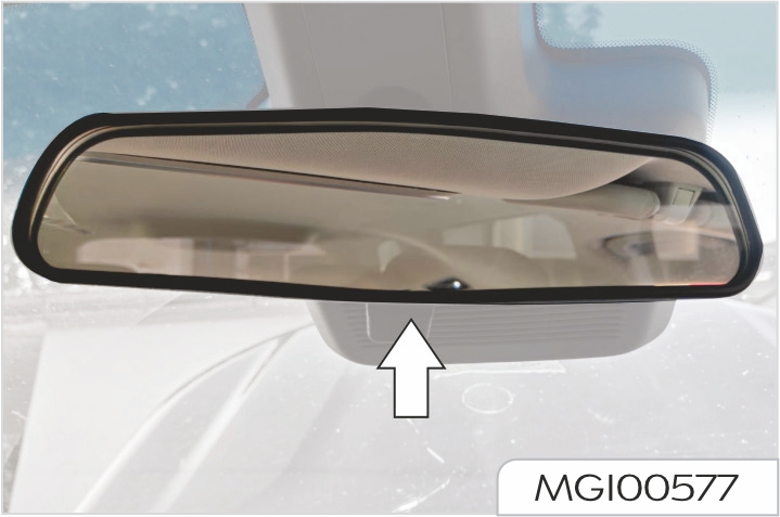
In some situations, using manual anti-dazzle function of interior rearview mirrors will enable the driver to have incorrect judgment of the position of vehicle behind.
Automatic anti-dazzle interior rearview mirrors
Type 1
For vehicles with automatic antidazzle interior rearview mirrors, after the vehicle is powered on, the automatic anti-dazzle function is automatically enabled, when the driver may be dazzled by the vehicle headlights behind, the light sensor enables the anti-dazzle function. After the vehicle power-off, the automatic anti-dazzle function is turned of
Automatic anti-dazzle function cannot be enabled normally in the following situations:
When the film is applied to the rear window glass, it may affect the usage of automatic anti-dazzle function.
Type 2
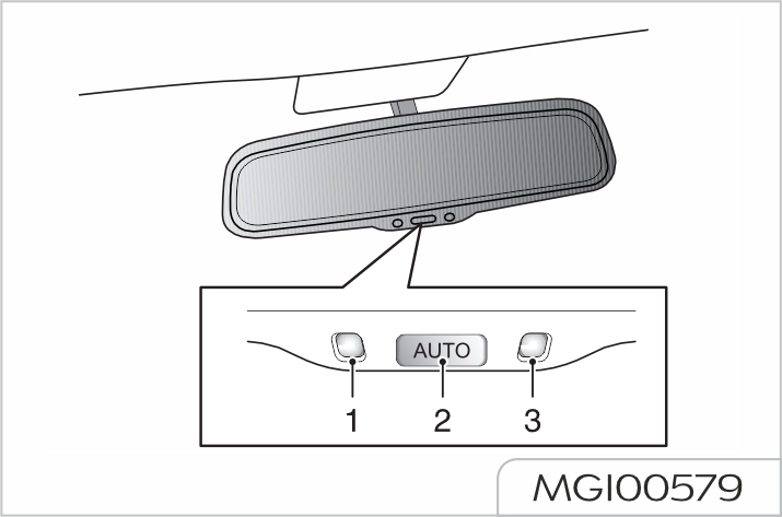
For vehicles with automatic antidazzle interior rearview mirrors, after the vehicle is powered on, press the automatic anti-dazzle function switch (2) at the bottom of rearview mirrors, the automatic anti-dazzle function is automatically enabled and the green working indicator (1) illuminates; when the driver may be dazzled by the vehicle headlights behind, the light sensor enables the antidazzle function. Press the automatic anti-dazzle function switch (2), the working indicator (1) goes out, and the automatic anti-dazzle function is turned off; press the switch again to re-enable this function.
Automatic anti-dazzle function cannot be enabled normally in the following situations:
When the film is applied to the rear window glass, it may affect the usage of automatic anti-dazzle function.
Streaming media interior rearview mirror
The streaming media rearview mirror takes images behind the vehicle through a camera installed at the rear part of the vehicle (near the left license plate light on the tailgate), and presents the images on the streaming media interior rearview mirror display in a lossless and delay-free manner. That is, it observes the actual situation behind the vehicle from the perspective of the camera.
The streaming media interior rearview mirror can greatly reduce the visual blind zone and improve the safety of driving.
For vehicles equipped with streaming media interior rearview mirror, the streaming media function will be enabled after the vehicle is powered on, and the real-time image behind the vehicle can be displayed.
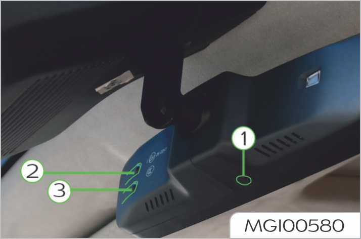
Long press the button (1) to switch between the states of automatic antidazzling interior rearview mirror and streaming media. In streaming media state, short press the button (1) to directly enter the function item adjustment interface (if it is pressed for the first time after the vehicle is newly powered on, it will enter the adjustment interface of the image upward/downward movement item; if it is not pressed for the first time after the vehicle is newly powered on, it will display the next item of the last function item in the previous function adjustment), and then short press the button (1) again to switch to the next function adjustment interface.
Methods for moving images up and down:
Methods for adjusting the view scaling:
Methods for adjusting the color:
It is dangerous to leave children, incapacitated adults or pets on the vehicle with windows closed.
They may faint out due to high temperature, or suffer permanent injury or even death due to heat stroke.
Do not leave children, incapacitated adults or pets on the vehicle with the windows closed, especially in the warm or hot weather.
Always take care when operating the power window.
There is a risk of injury, especially for children.
Please pay close attention when closing the window.
Ensure that no objects are stuck in it while the window is moving.
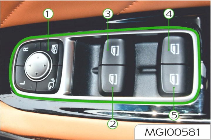
Press the switches (2) to (5)
![]() , to
lower the window glass; lift the switch,
to move the window glass up. Release
the switch, and the window stops
working (except for "One-button"
mode).
, to
lower the window glass; lift the switch,
to move the window glass up. Release
the switch, and the window stops
working (except for "One-button"
mode).
The front door and side load door windows can also be controlled by using the window switch on each door. If the rear window disable switch on driver door is activated, the window control switch on the side load door does not work.`
Rear window disable switch
Press the switch (1)
![]() to disable the
window control (the indicator on the
switch illuminates at this time), and
press the switch again to resume the
control.
to disable the
window control (the indicator on the
switch illuminates at this time), and
press the switch again to resume the
control.
When a child sits on the rear seat, the disable function shall be enabled.
Window control switch on side load door
Press the switch (1)![]() to close
the side load door window at the
corresponding side, and press the
switch (2)
to close
the side load door window at the
corresponding side, and press the
switch (2)![]() to open the side load
door window at the corresponding
side.
to open the side load
door window at the corresponding
side.
The power window can operate only when the vehicle is powered on.
Please operate the windows correctly to avoid danger, and the driver should provide guidance on usage of windows and safety precautions.
Automatic up/down function of window
"One-button" down
Window control switches (2) to (5)
![]() have two positions, short press to
the second position, and the window
automatically opens. During the
window glass down process, operate
the switch again to stop the window
glass moving down.
have two positions, short press to
the second position, and the window
automatically opens. During the
window glass down process, operate
the switch again to stop the window
glass moving down.
"One-button" up and "Anti-pinch"
The right front door window has
"One-button" up function; briefly lift
the window control switch (3)
![]() to
the second position, and the window
glass automatically moves up to close;
operate the switch again to stop the
movement of window glass at any
time.
to
the second position, and the window
glass automatically moves up to close;
operate the switch again to stop the
movement of window glass at any
time.
"Anti-pinch" function is a kind of safety function, which can allow the window glass to stop moving up when obstacles are sensed.
If this situation occurs, the window glass will automatically moves down to take out obstacles.
The left front door window and side load door window of some models also have "One-button" up and "Antipinch" functions, whose operation methods are the same as those of right front window.
Micro switch on door handle
Long press the micro switch on door handle to automatically close the windows of front rows.
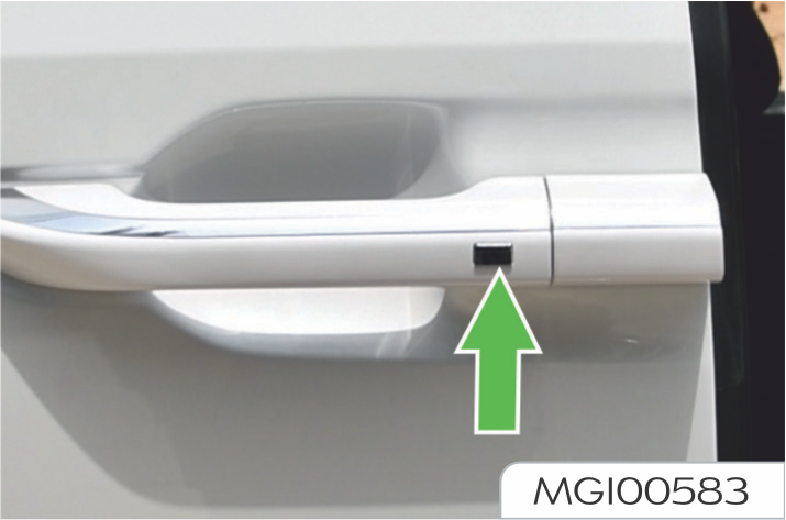
For the function of "long press the micro switch on door handle to automatically close the windows of front rows", please refer to the actual configuration of your vehicle.
Resume the automatic up/down function
If the vehicle battery cable is reconnected after the disconnection, or the battery was drained once, or the anti-pinch function has been enabled for 3 consecutive times at the same position when the window glass moves up, the automatic up/ down function may not work, it must be re-learned to restore the function. Close all doors, pull up the window up/down switch, until the window is fully closed, hold the switch for about several seconds after the window is fully closed; then press the window up/down switch until the window is fully open, hold the switch for about several seconds after the window is fully open, the automatic up/down function will be recovered.
It applies to vehicles configured with power sunroof
Instructions
Do not allow occupants to extend any part of their bodies out of the sunroof while driving - to avoid injuries caused by flying objects or tree branches.
When operating the sunroof, be sure to keep persons in the vehicle safe, especially children; do not put any part of body or objects into the sunroof, to prevent being pinched by the sunroof
The power window can operate only when the vehicle is powered on.
Operation method of front sunroof
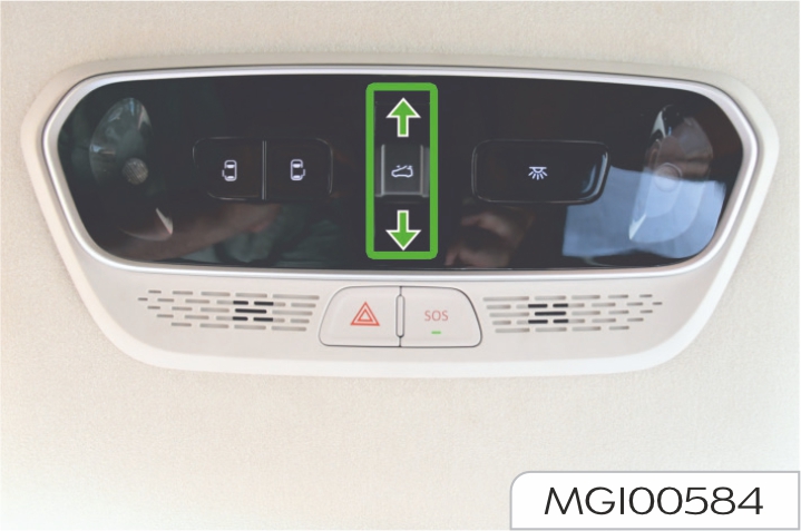
Press the front sunroof opening button (1) once, and the front sunroof will be lifted to the position for ventilation.
The front sunroof will be opened manually when the button (1) is pushed toward the rear of the vehicle by one gear; the front sunroof will slide to the fully open position when the button (1) is pushed toward the rear of the vehicle by two gears.
The front sunroof will be closed manually when the button (1) is pushed toward the front of the vehicle by one gear; the front sunroof will slide to the fully closed position when the button (1) is pushed toward the front of the vehicle by two gears.
During the automatic operation, the button (1) can be pressed once, to make the sunroof stop at the required position.
Front sunroof initialization
With the front sunroof in the fully closed position, press and hold the button (1) for more than 10 seconds toward the front of the vehicle, at this time, the sunroof will move toward the opening direction, then move toward the closing direction after reaching a certain position. Continue to press and hold the button (1) until the front sunroof glass is fully closed, then release the switch again, thus the initialization operation of the front sunroof has been completed.
During the initialization process, if you inadvertently release the button (1), resulting in the loss of automatic opening and closing function of the front sunroof, just repeat the initialization operation and it will return to normal after completion. If repeated operations still fail to restore the front sunroof, please contact Our Service Dealer for service.
Operation method of panoramic sunroof
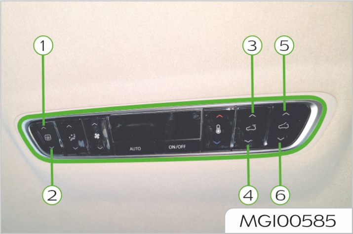
The sunshade opening/closing switch has auto and jog functions, which can conveniently control the opening and closing process of sunshade. Short press the switch, to open or close the sunshade in jog mode; long press the switch to automatically open or close the sunshade.
Panoramic sunroof initialization
When the panoramic sunroof movement logic disorder occurs, manual initialization operation can be performed to restore the panoramic sunroof movement to normal.
With the panoramic sunroof glass
fully open and the sunshade fully
open, long press![]() panoramic
sunroof opening switch (3) for about 10 seconds, then the
panoramic
sunroof opening switch (3) for about 10 seconds, then the
sunroof glass
will begin to close; after the glass
are fully closed, the sunshade will
begin to close. While the sunroof
glass and sunshade are running,
press and hold![]() the panoramic
sunroof opening switch (3) until the
sunroof glass and sunshade are
fully closed, then release the switch
again, thus the initialization operation
of the panoramic sunroof has been
completed.
the panoramic
sunroof opening switch (3) until the
sunroof glass and sunshade are
fully closed, then release the switch
again, thus the initialization operation
of the panoramic sunroof has been
completed.
During the initialization process, if
accidentally release the panoramic
sunroof opening switch (3)
![]() , causing the loss of automatic
opening and closing function of
the panoramic sunroof, at this
time, it is only required to repeat
the initialization operation, and
the function will return to normal
after the completion. If repeated
operations still fail to restore the
panoramic sunroof, please contact
Our Service Dealer for service.
, causing the loss of automatic
opening and closing function of
the panoramic sunroof, at this
time, it is only required to repeat
the initialization operation, and
the function will return to normal
after the completion. If repeated
operations still fail to restore the
panoramic sunroof, please contact
Our Service Dealer for service.
If it is found that the sunroof glass
cannot be opened when it is not fully
open, try to long press
![]() button, at
this time, the sunroof will open in jog
mode to full open, and then you can
perform the initialization operation.
If you long press
button, at
this time, the sunroof will open in jog
mode to full open, and then you can
perform the initialization operation.
If you long press![]() button and the
sunroof still does not work, in this
state, please long press
button and the
sunroof still does not work, in this
state, please long press
![]() for 10
seconds, to perform the initialization
operation directly. If repeated
operations still fail to restore the
panoramic sunroof, please contact
Our Service Dealer for service.
for 10
seconds, to perform the initialization
operation directly. If repeated
operations still fail to restore the
panoramic sunroof, please contact
Our Service Dealer for service.
Front roof vanity light

Press the switch (1) vanity lights on both sides and rear roof vanity light illuminate at the same time; press the switch (1) again, and the vanity lights on both sides and rear roof vanity light go out at the same time.
Touch light-emitting area of (2) with hands, and the left vanity light illuminates; touch light-emitting area of (2) again with hands, and the left vanity light goes out.
Touch light-emitting area of (3) with hands, and the right vanity light illuminates; touch light-emitting area of (3) again with hands, and the right vanity light goes out.
(2) and (3) on the front roof vanity light are capacitive touch buttons; for daily touch usage, please touch the middle area. When touching, it's required to touch middle areas of (2) and (3) with a slight force with finger pulp, and it's recommended that the touch time should last for more than 1s. After touching, the finger is required to be more than one fist away from the touch pad, and touch the roof light at least 2 seconds apart.
Rear roof vanity light
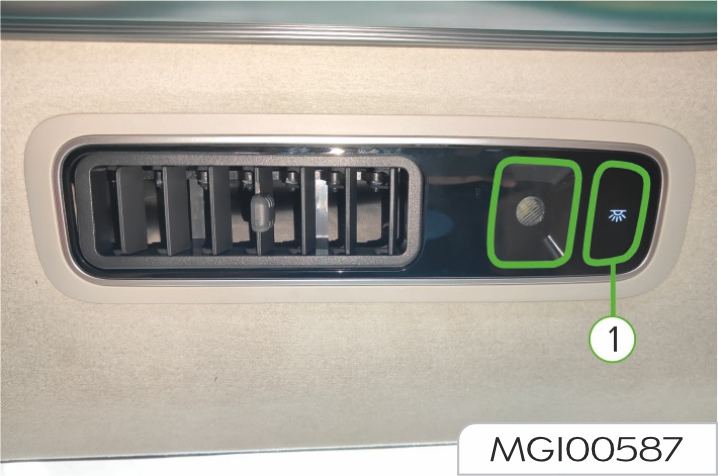
Press the switch (1) , and the rear roof vanity light illuminates; press the switch (1) again, and the rear roof vanity light goes out.
The rear roof vanity light will illuminate when any door is opened and will go out automatically about 30s after the door is closed. The roof vanity light will go out automatically about 15 minutes after any door is opened to avoid lack of battery power.
The trunk light will automatically illuminate when the trunk lid is opened and will go out when the trunk lid is closed.
The trunk light will automatically go out when the trunk lid is kept open for more than 15 minutes.

The corresponding stepwell light illuminates when the sliding door is opened. The stepwell light will go out when the door is closed.
The stepwell light will automatically go out about 15 minutes after the slide door is opened avoid lack of battery power.
It applies to vehicles configured with the multi-color atmosphere light.
The multi-color atmosphere lights may be located on the roof and front/ rear door. Their position on your vehicle depends on the actual vehicle configuration you purchased.
The touch buttons on the central control screen can be used to control the on/off, color, brightness and illumination mode of multi-color atmosphere lights.
Multi-color atmosphere light has several subdivided intelligent scene functions, including: vehicle startup feedback, welcome and see off mode, incoming call reminder, voice interaction, music follow-up, and vehicle speed rhythm.
You may set the lighting effects of multi-color atmosphere light for different scenes according to personal preference and lighting requirements, to configure a comfort function and safety alarm function in the vehicle.
USB ports are located at the front windshield, below the dashboard, in the storage box under the auxiliary fascia console armrest, at the 2nd row single seat side, and on the 3rd row body-side panel. The position of USB ports on your vehicle shall be subject to the actual configuration of the vehicle you purchased.
Please do not use the USB port for a long time when the vehicle is powered on but has not started, which may cause the battery to lose power.
USB port at front windshield
USB port at front windshield can be used for charging.
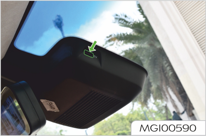
USB port located below dashboard
The left USB port below the dashboard can provide charging function; the right USB port below the dashboard can also provide charging function and play multi-media files.
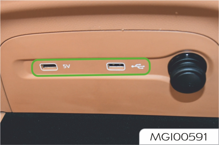
USB port in storage box under auxiliary fascia console armrest
The USB port in the storage box under auxiliary fascia console armrest can be used for charging and playing multi-media files.

USB port at 2nd row manually adjustable right single seat side
USB port at the 2nd row manually adjustable single seat side can be used for charging.
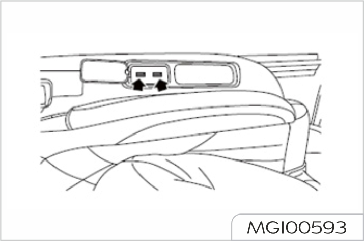
USB port and Type-C port at 2nd row electrically adjustable right single seat side
USB port and Type-C port at the 2nd row electrically adjustable right single seat side can be used for charging.
USB interface on the third-row side panel
USB port on 3rd row body-side panel can be used for charging.

It applies to vehicles configured the 12V power socket.
The power sockets are located at the auxiliary fascia console and the right side of the trunk, which are mainly used for providing power supply connection for external electric devices.
The position of 12V power socket on your vehicle shall be subject to the actual configuration of the vehicle you purchased.
Please do not use the power socket for a long time when the vehicle is powered on but has not started, which may cause the battery to lose power.
The power socket can provide power supply for electric devices of which power is no more than 120W.
12V power socket at auxiliary fascia console

12V power socket at the right side of trunk
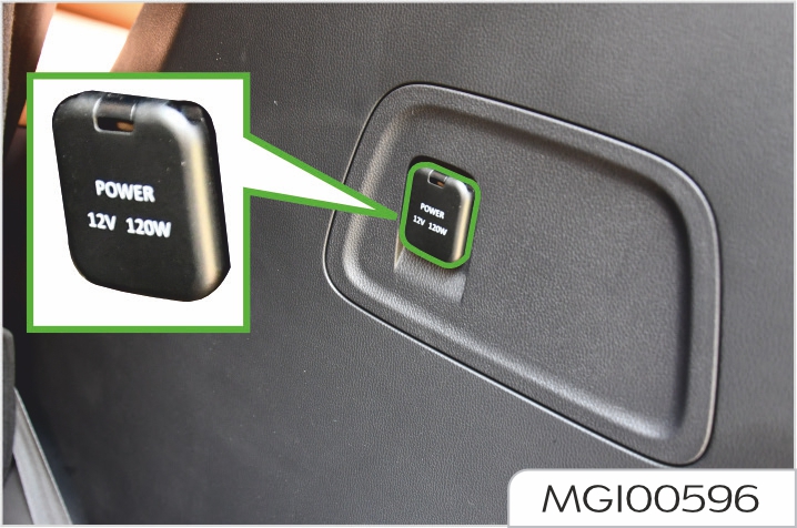
It applies to vehicles configured with the wireless charging system for mobile phone.
If your vehicle is configured with wireless charging system for mobile phone, then the system will enable mobile phone to be charged wirelessly through electromagnetic induction without wires connected.
The wireless charging system does not apply to all mobile phones, but only to the "Qi" certified mobile phones.
Operations for mobile phone wireless charging
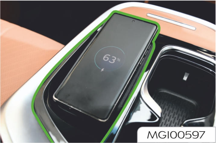
Place the mobile phone as shown in the figure above (with the screen forward), with the center of mobile phone aligned to the charging symbol.
When the mobile phone is being charged, the charging status icon will be displayed on the status bar of central control screen (There are also corresponding status icons to indicate completed charging and charging fault). When the vehicle stalls and
the doors are closed, if the vehicle detects that the mobile phone is still being charged, it will remind the driver to never forget the mobile phone through pop-up window on the central control screen and prompt tone.
When the low-frequency antenna of PEPS system searches for key, the mobile phone wireless charging module may stop operating.
Please do not use the wireless charging system for mobile phone for a long time when the vehicle is powered on but has not started, which may cause the battery to lose power.
Failure of mobile phone wireless charging
In case of any failure during charging, it may be caused by the followings:
It applies to the vehicles equipped with the on-board inverter.
Please pay attention to electric safety during usage.
Prevent children from contacting this outlet. Danger!
High voltage!
Do not insert finger or a conductive object into this outlet. Please keep liquid objects away from this outlet.
Do not use it in a humid, hot (more than 850C) and unventilated environment.
The maximum rated power of inverter is 150W. Do not use any electric appliance with a power more than 150W.
On-board inverter is located behind the auxiliary fascia console. Open the panel, and you will see the 220V AC power outlet, which can provide an output power of 150W. During usage, please pay attention to the indicator showing the power supply operating state near the outlet, and operate according to the prompts provided by the indicator:
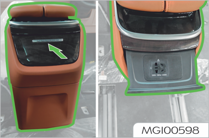
Please do not use the on-board inverter for a long time when the vehicle is powered on but has not started, which may cause the battery to lose power.
Do not stow sharp, heavy or dangerous objects in the glove box at the passenger side.
Driving with the glove box open may cause injury in the event of an accident or sudden stop. Keep the glove box closed when driving.
Lift the flap handle to open the box. Close it with a firm push.
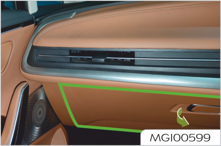
Front compartment storage box
It is below the front compartment hood. Pull up twice the unlock handle of front compartment hood below the instrument desk on the driver side to unlock the front compartment, and lift the front compartment hood. Pull up the storage box buckle to open the front compartment storage box.
Please close the front compartment hood after closing the front compartment storage box.
The storage weight shall not be more than 25kg.
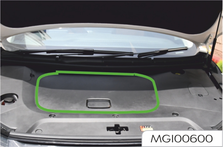
Storage box on the driver side
It is located below the instrument desk on the driver side, and can be opened by pulling down the storage box buckle.

Storage box below the armrest of auxiliary fascia console
When the unlock button is pressed, the left and right armrest panels will eject to both sides to open the storage box. The armrest storage box of central control console can be closed by putting down the armrest.
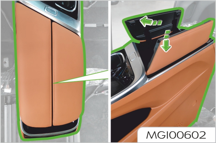
Storage box at the rear bottom of auxiliary fascia console
It is a drawer-type storage box which can be opened by pulling back the storage box buckle.
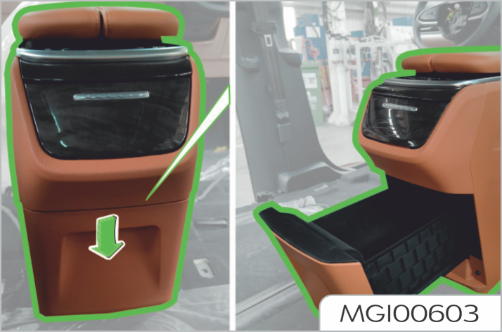
Both sun visors can be swung up and down to provide a shield through the windshield. Besides, sun visors can be rotated towards side windows. Turn a sun visor downwards and open the vanity mirror cover. Then you can use the vanity mirror. Driver's vanity mirror shall be used only when the vehicle stops.
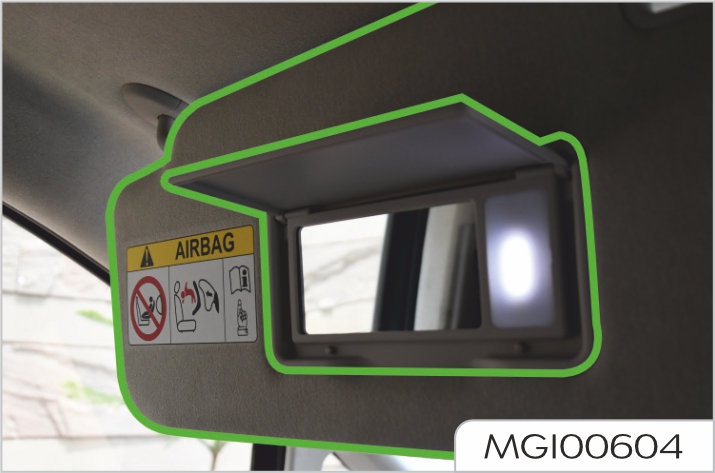
It applies to the vehicles equipped with the sunshade.
Pull up the tab of the sunshade and hook the sunshade with the fixing device.
To retract the sunshade, unhook the sunshade and retract it slowly
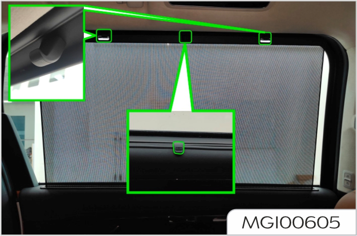
To ensure normal operation of the sunshade, please observe the following precautions:
The vehicle tool is placed in the front compartment storage box.
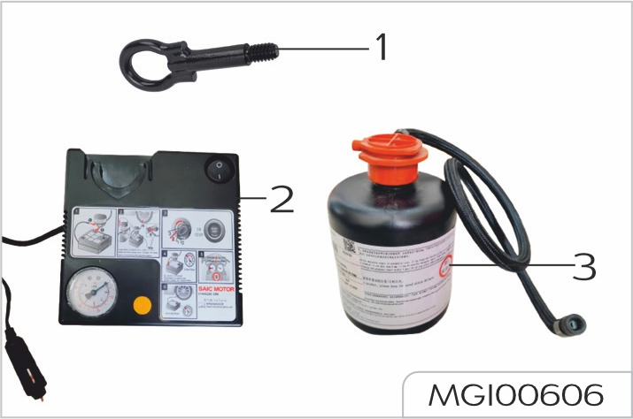
The air conditioning system cools the air and removes moisture and dust e.g. pollen.
The heating system utilizes highpressure electronic heater, therefore, the interior air heating function is only available when the vehicle is under high pressure.
The ventilation system ensures the interior ventilation when the vehicle is moving.
The front/rear A/C air volume selection button is used to control the air volume.
HVAC is used to control the interior air cooling, heating and ventilation. Fresh air enters the vehicle through the air inlet grille under the windshield and flowing through the A/C filter. Always keep the air inlet grille clean and free of obstructions such as leaves, snow or ice.

Central vents
For vehicles with manually adjusted vents, move the lever (1) in the center of the grille up and down, right and left to change the direction of the air blowing.

Side vents
For vehicles with manually adjusted vents, move the lever in the center of the grille up and down, right and left to change the direction of the air blowing.

For vehicles with electrically adjusted vents, please enter the setting interface on the center console screen for adjustment.
The direction of air flow can be changed by revolving the grille or moving the plate (1) in the center of the grille. There are four vents on the roof, two on the right and left, respectively.
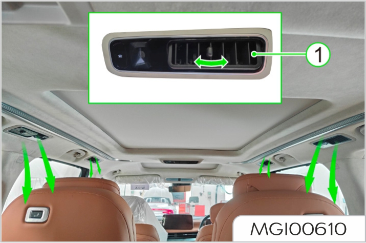
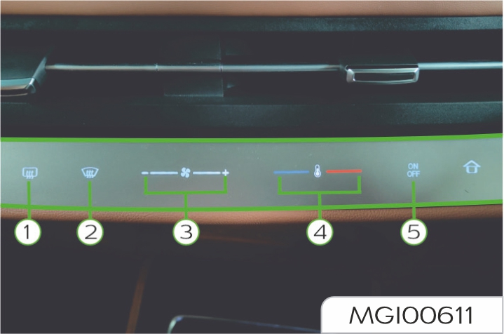
Power button
Air conditioning on/off button.
If the indicator illuminates, it indicates that the air conditioner is on, and the air conditioning functions will be enabled according to the status before shutdown, if the indicator goes out, it indicates that the air conditioner is off, and the air blower, compressor and other air conditioning functions are disabled.
Temperature adjusting slider
Adjust the A/C setting temperature.
With the panel turned on, the set temperature decreases when you slide to the left or click on the left; the set temperature rises when you slide to the right or click on the right. Temperature adjusting range: LO (170C), 180C - 320C and HI (330C).
Air volume adjusting slider
To control the blower speed.
With the panel turned on, the set air volume decreases when you slide to the left or click on the left; the set air volume rises when you slide to the right or click on the right. There are 8 gears for air volume adjusting.
Front defrost button
Switch on the front defrost state.
When the front defrost button is operated, the corresponding indicator illuminates, A/C is turned on at the same time, and the air outlet mode is switched to defrost; turning on this function has a rapid defrost and defog
effect on the front windshield and side glass. In the front defrost state, press the front defrost button or other mode buttons again to exit the defrost state.
Rear defrost button
Switch on the rear defrost state.
When the rear defrost button is operated, the corresponding indicator illuminates, and the rear defrost function is enabled; turning on this function has a rapid defrost and defog effect on the rear windshield.
For vehicles with heated exterior rearview mirrors, the function of heated exterior rearview mirror will be enabled when the Rear Defrost button is pressed, to help remove fog or frost from the surface of the rearview mirror.
The rear defrost will stop after operating for 15 minutes, and its indicator goes off.
Front row A/C interface
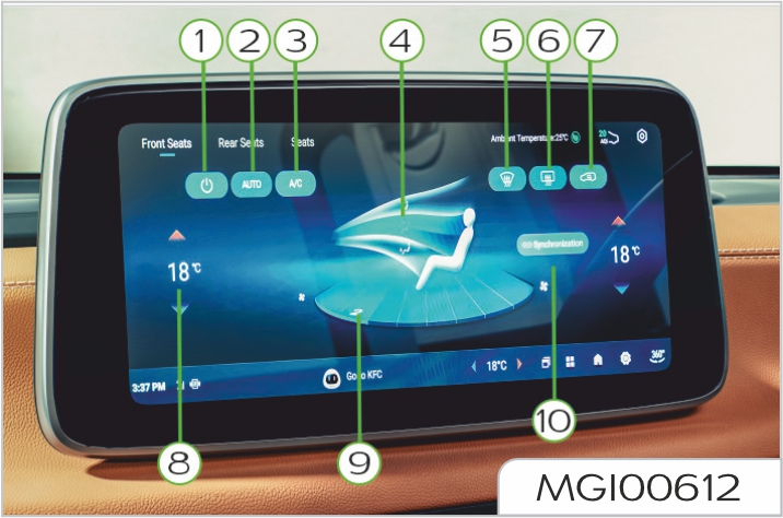
Rear row A/C Interface
Type 1
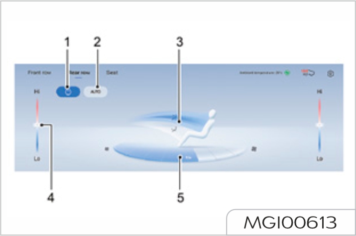
Type 2
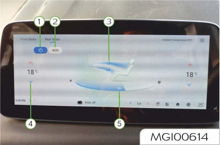
Power button
Air conditioning on/off button.
If the indicator illuminates, it indicates that the air conditioner is on, and the air conditioning functions will be enabled according to the status before shutdown; if the indicator goes out, it indicates that the air conditioner is off, and the air blower, compressor and other air conditioning functions are disabled.
Temperature adjusting button
The front row A/C temperature adjusting button is used to adjust the required temperature of left/right A/C of front row A/C. The rear row A/C temperature adjusting button is used to adjust the required temperature of rear row A/C.
In any season, after the air conditioner is turned on, the A/C state will be adjusted as soon as possible, so that the temperature in the vehicle reaches the set temperature and remains stable.
There are 17 gears for temperature selection range; when the temperature is set to LO, the air conditioner is in the highest refrigerating power state; when the temperature is set to HI, the air conditioner is in the highest heating power state.
The set temperature of automatic air conditioner is between 220C and 240C, which is the recommended comfortable temperature.
If brief and continuous switching is performed between different set temperatures, the automatic air conditioner has no adequate time to be adjusted to the set temperature.
SYNC button
Synchronous temperature selection.
When the button illuminates, the set temperature at the front occupant side will be synchronized to the same as that at the driver side; when the temperature at the driver side is adjusted, the temperature at the front occupant side will change with it.
If the temperature at the front occupant side is adjusted individually, the temperature at the driver side will not change with it, the SYNC indicator goes out, and exits the SYNC state.
AUTO button
Turn on the automatic A/C function.
Press the AUTO button to enter the fully automatic state of the air conditioner, and the air volume, mode, circulation and other functions enter the automatic working state. In this case, the temperature adjusting button can be operated as needed for comfort level to set the required temperature, based on which the A/C system will automatically adjust the vehicle environment, in order to reach the target temperature and maintain stability in the vehicle at the maximum speed.
In AUTO state, when the mode, air volume and A/C buttons are operated, the AUTO indicator goes out, the corresponding functions will exit the AUTO state, and other unoperated functions will remain in auto state.
A/C button
Switch on and off the compressor.
Operate the A/C button to illuminate the corresponding indicator; the air conditioner will turn on the compressor to cool the air in the vehicle, and has a certain dehumidification function.
The A/C indicator is always on in AUTO state (in automatic control state, which does not indicate that it is operating); if the A/C button is operated, A/C will exit the AUTO state and enter the state of manual control. The compressor can only operate when the motor is operating.
Air outlet mode button
Adjust the air blowing mode.
Front row A/C air outlet mode is divided into face, footwell and window modes. Rear row A/C air outlet mode is divided into face and footwell modes. The corresponding indicator illuminates, indicating that there is air outlet in this direction, and you can freely combine air outlet modes according to needs.
It's recommended to blow the face with cool wind in summer, blow the feet with hot wind in winter, and blow the window when there is fog on the front windshield, which is more convenient for improving the comfort level in the vehicle.
Air volume adjusting button
To control the blower speed.
There are 8 gears for air volume adjusting; air volume can be adjusted according to requirements for comfort level. When the air conditioner is turned off, the A/C system can be turned on by setting air volume.
Internal / external circulation button
Internal / external circulation is switched through the button.
Operate the button to switch the A/C air inlet mode; external circulation indicates that the air enters the air conditioner from outside, and internal circulation indicates that the air circulates in the vehicle.
Internal circulation is recommended when refrigeration is required; external circulation is recommended when heating is required.
Front defrost button
Switch on the front defrost state.
When the front defrost button is operated, the corresponding indicator illuminates, A/C is turned on at the same time, and the air outlet mode is switched to defrost; turning on this function has a rapid defrost and defog effect on the front windshield and side glass. In the front defrost state, press the front defrost button or other mode buttons again to exit the defrost state.
Rear defrost button
Switch on the rear defrost state.
When the rear defrost button is operated, the corresponding indicator illuminates, and the rear defrost function is enabled; turning on this function has a rapid defrost and defog effect on the rear windshield.
For vehicles with heated exterior rearview mirrors, the function of heated exterior rearview mirror will be enabled when the Rear Defrost button is pressed, to help remove fog or frost from the surface of the rearview mirror.
The rear defrost will stop after operating for 15 minutes, and its indicator goes off.
Automatic defog button
After this function is turned on, the A/C system will automatically adjust its state according to interior humidity and temperature, to avoid fog on the glass inside the vehicle, and the effect will be better after A/C "AUTO" is turned on.
Bluetooth phone noise-reduction button
After this function is turned on, the A/C system will automatically decrease the air volume when Bluetooth phone is connected, so as to reduce the noise effect.
Maximum air volume limit button
After this function is turned on, the A/C system air volume will be limited in "AUTO" and "Front Defrost" modes, with the maximum not exceeding that in 7/6/5 gear
Automatic fresh air switch time button
After this function is turned on, and internal/external circulation is in "AUTO" state, the A/C system will automatically switch the circulation mode every 10/20/30 minutes, to ensure that interior air is fresh.
Off-car ventilation button
After this function is turned on, if A/C (compressor) is in working state before vehicle shutdown, the A/C system will turn on the blower again 30s after vehicle shutdown, and continue to blow air for 1 minute and dry the evaporator, to prevent the growth of mold.
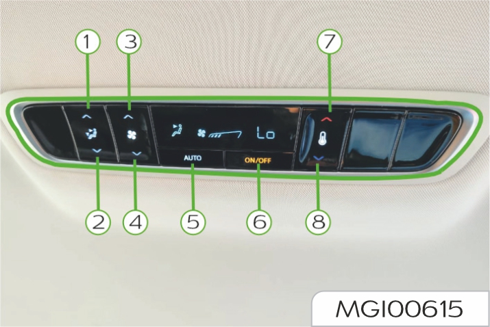
Air outlet mode button
Adjust the air blowing mode.
A/C air outlet mode is divided into face, face/footwell and footwell modes; adjust up/down to switch air outlet mode in order; it's recommended to blow the face with cool wind in summer and blow the feet with hot wind in winter, which is more convenient for improving the comfort level in the vehicle.
Air volume adjusting button
To control the blower speed.
There are 8 gears for air volume adjusting; air volume can be adjusted according to requirements for comfort level. Press the blower speed increase button (3), to increase the blower speed; press the blower speed decrease button (4), to decrease the blower speed.
When the air conditioner is turned off, the A/C system can be turned on by setting air volume.
AUTO button
Turn on the automatic air conditioner.
Press the AUTO button (5) to enter the fully automatic state of the air conditioner, and the air volume, mode and other functions enter the automatic working state. In this case, the temperature adjusting button can be operated as needed for comfort level to set the required temperature, based on which the A/C system will automatically adjust the vehicle environment, in order to reach the target temperature and maintain stability in the vehicle at the maximum speed. operated, the AUTO indicator goes out, the corresponding functions will exit the AUTO state, and other unoperated functions will remain in auto state.
Power button
Air conditioning on/off button.
Press the power button (6), and indicator illuminates, indicating that the air conditioner is turned on, and the A/C function will be enabled according to the status before shutdown; press the power button (6) again, and indicator goes out, indicating that the air conditioner is turned off, and the air blower and other A/C functions are disabled.
Temperature adjusting button
Adjust the required temperature of rear row A/C.
In any season, after the air conditioner is turned on, the A/C state will be adjusted as soon as possible, so that the temperature of rear row A/C reaches the set temperature and remains stable. There are 17 gears for temperature selection range; press the temperature increase button (7), to increase the set temperature; press the temperature decrease button (8), to decrease the set temperature. When the temperature is set to LO, the air conditioner is in the highest refrigerating power state (it's required to turn on the front A/C in the highest refrigerating mode); when the temperature is set to HI, the air conditioner is in the highest heating power state.
The set temperature of automatic air conditioner is between 220C and 240C, which is the recommended comfortable temperature.
If brief and continuous switching is performed between different set temperatures, the automatic air conditioner has no adequate time to be adjusted to the set temperature.
If the air conditioning will not be in use for more than one month, run the vehicle at idle speed and turn on the system for more than 10 minutes (once every month, including in winter). This aims to maintain the proper lubrication of the compressor and the seals, so as to extend the service life of the system.
Condensation will be formed on the evaporator when the A/C is operating. So you may find a small pool of water under the vehicle after the vehicle is stopped.
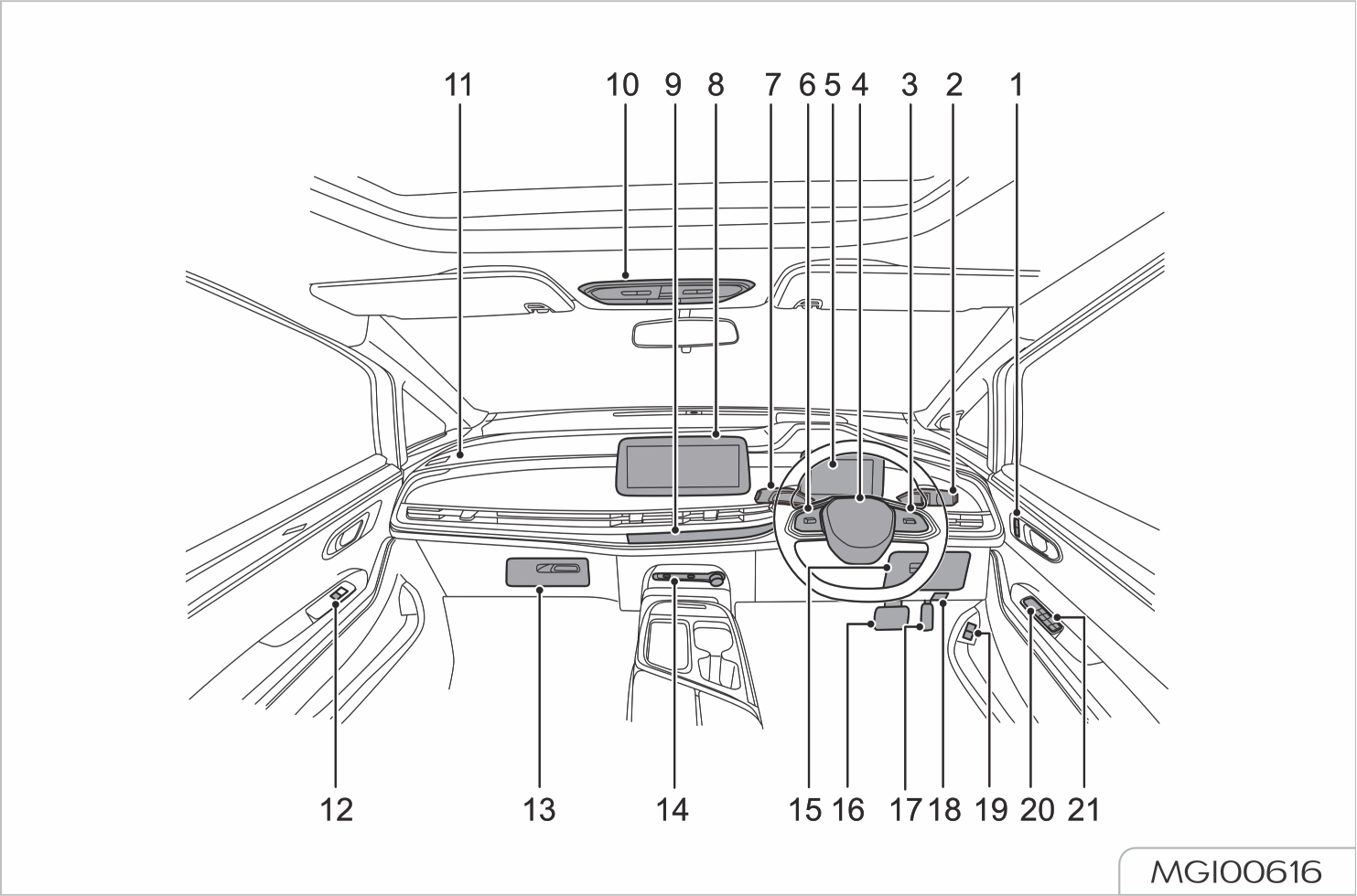
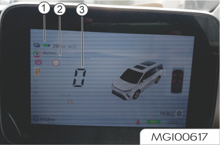
Don't place any object in front of the instrument cluster to avoid shielding dial and warning light.
The state of voltameter of highvoltage battery pack will be indicated based on the proportion of ignited battery icons. When the electric quantity of the battery is too low, the red strip-type bar will light up, and "warning lamp of high-voltage battery pack for low electric quantity (yellow)" will also light up.
Low electric quantity of highvoltage battery pack will make some functions of the vehicle lose effect.
When the electric quantity of highvoltage battery pack is low, the battery will be charged as soon as possible.
Ensure enough electric quantity is stored in high-voltage battery pack before running. After the vehicle is fully charged, Battery Management System will have automatic calibration function. After the vehicle has been shallowly charged (less than 99%) every two to three times, the vehicle needs to be fully charged for once (100%).
The speedometer indicates the current road speed in kilometers per hour. ~
The power meter shows the power percentage of power system. Power indication range is -25~100%, and the maximum and minimum will be shown if they are exceeded.
The power meter indicates the power percentage, not the calculated actual power.
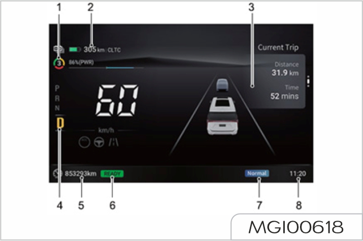
It indicates the energy recovery level of current vehicle, and the energy recovery level is divided into three levels of high, medium and low, which are numerically displayed on the instrument pack as 3, 2 and 1. High-level energy recovery is larger than the medium-level energy recovery, while the medium-level energy recovery is larger than the lowlevel energy recovery. The energy recovery level can be switched through energy recovery switch on the central control screen.
It displays the estimated mileage that the vehicle can run before the electric quantity of high-voltage battery is used up.
With the vehicle powered on, when the vehicle ready indicator lamp "READY indicator lamp (green)" lights up, it indicates the power system is ready for driving.
It displays the current driving mode of the vehicle: ECO (economy mode), SPORT (sport mode) and Normal (normal mode). The driving mode can be switched by the driving mode switch on the central control screen.
Short press the instrument
cluster selection switch
![]() on the steering wheel to the left
and right to switch between
the following interfaces: Simple
interface→ADAS (Advanced Driver
Assistance System) interface→Trip
computer interface→Fault inquiry
interface (if in fault)→Simple
interface.
on the steering wheel to the left
and right to switch between
the following interfaces: Simple
interface→ADAS (Advanced Driver
Assistance System) interface→Trip
computer interface→Fault inquiry
interface (if in fault)→Simple
interface.
If the vehicle is not equipped with the relevant function, the interface will not be displayed.
Trip computer interface
Short press up and down the
instrument cluster selection switch
![]() on the steering wheel to
switch between the following interface
contents:
on the steering wheel to
switch between the following interface
contents:
It displays the instantaneous power consumption when the battery is working.
It displays the driving distance and driving time since the vehicle is powered on to start.
It displays the driving distance and driving time since the last reset.
In this interface, long press the
instrument cluster selection switch
![]() to reset the driving
distance and driving time.
to reset the driving
distance and driving time.
ADAS (Advanced Driver Assistance System) interface (if available on your vehicle)
It displays the relevant information of driver assistance system configured on your vehicle.
Fault inquiry interface
Short press up and down the instrument cluster selection switch on the steering wheel to switch between the following interfaces: the relevant fault messages for vehicle warning can be inquired on this interface (if no fault, the interface will not be displayed).
Most of alarm messages will have a corresponding graphic and text description in the instrument cluster. The warning light will illuminate to display messages.
If more than one alarm message is activated, the alarm messages will be displayed in a cycle by priority, and each alarm message will be displayed for 3 seconds.
The priority for alarm message is higher than that for trip computer message, and after the vehicle is powered on, the alarm message will be displayed by priority.
Please operate in strict accordance with the instructions in the alarm message. If there is relevant instructions, please stop the vehicle for inspection or consult Our Service Dealer.
Important alarm messages
The currently displayed important
alarm message can be temporarily
shielded by short pressing the
instrument cluster selection switch
![]() or automatically shielded 9
seconds later. It can also be viewed in
the alarm query interface if the alarm
is not cancelled.
or automatically shielded 9
seconds later. It can also be viewed in
the alarm query interface if the alarm
is not cancelled.
If all the alarm messages are shielded, the trip computer message will be displayed normally.
When the conditions of alarm activation are cancelled, the corresponding alarm messages are also cancelled to display
Indicative messages
Indicative messages disappear automatically after 3 seconds.
Don't neglect the alarm messages, otherwise it may cause serious damage to the vehicle. If the alarm indicator is on, please stop the vehicle as soon as possible if it is safe to do so.
Next maintenance reminder
When the message center of instrument cluster displays “XXkm remained before the next maintenance”, it reminds you of the remaining mileage of your vehicle before the next maintenance.
Imminent maintenance reminder
When the message center of instrument cluster displays “Maintenance period is imminent, please make maintenance as soon as possible”, it reminds you to go to Our Service Dealer for maintenance as soon as possible.
Service now reminder
When the message center of instrument cluster displays “Please make service now”, it reminds you that the vehicle needs service now and you should go to Our Service Dealer for maintenance as soon as possible.
Maintenance overdue reminder
When the message center of instrument cluster displays “Maintenance is overdue, please make immediate maintenance”, it reminds you that the vehicle maintenance is overdue and you should go to Our Service Dealer for maintenance immediately.
The tyre pressure monitoring system automatically monitors the tyre conditions in real time, providing effective safety guarantee for driving.
When the tyre pressure is insufficient,
too high, or the tyre leaks quickly
or the system fails in the course of
driving, the "TMPS warning light
(yellow)”
![]() on the instrument cluster
illuminates with voice prompt, and
the instrument display shows the
corresponding alarm interface.
on the instrument cluster
illuminates with voice prompt, and
the instrument display shows the
corresponding alarm interface.
Direction indicator
The left or right "direction indicators (green)" flash when making a turn. When the hazard warning light switch is pressed, the left and right direction indicators flash simultaneously.
If a direction indicator flashes rapidly, it indicates that the bulb in this direction indicator is faulty.
Headlight high beam indicator
The "headlight main beam indicator (blue)" illuminates when the headlights are on main beam or flash on.
IHC (Intelligent High Beam Control) indicator
It applies to vehicles configured with IHC.
With the vehicle powered on, when IHC system controls the high beam to illuminate, "IHC indicator (blue)" illuminates; when IHC system controls the high beam to go out, "IHC indicator (grey)" illuminates. See "IHC (Intelligent High Beam Control)" in the Starting and Driving section for more information.
Rear fog light indicator
The "rear fog light indicator (yellow)" illuminates when the rear fog lights are on.
Position light indicator
The "position light indicator (green)" illuminates when the position lights are on.
IMMO warning light
With the vehicle powered on, if the immobilizer authentication is successful, the "IMMO warning light (yellow)" will go out and the vehicle can be started.
If the "IMMO warning light (yellow)" flashes, it indicates that the immobilizer control system is faulty, and the vehicle cannot be started. Please contact Our Service Dealer for service immediately.
TPMS warning light
With the vehicle powered on, when the TPMS breaks down, the "TPMS warning light (yellow)" will illuminate. Please contact Our Service Dealer for service.
Battery charging indicator
With the vehicle powered on, the "battery charging indicator (red)" illuminates, and goes out after the vehicle is started.
If the warning light stays on after the vehicle is started or illuminates during driving, it indicates that the charging system has a malfunction, please contact Our Service Dealer for service as soon as possible.
READY indicator
This light is used to indicate that the vehicle is ready for running. After the vehicle is started, the "READY indicator (green)" will illuminate and will not go out in the running process.
Charging connection indicator
After charging handle is connected to charging interface, the "charging connection indicator (red)" will illuminate.
Charging status indicator
When the high-voltage battery pack is being charged, the "Charging status indicator (yellow)" will illuminate. When the high-voltage battery pack has been charged, this indicator will go out.
If the "charging status indicator (yellow)" flashes, it means that battery is faulty and it cannot be charged.
Contact Our Service Dealer for service as soon as possible.
Power system fault warning light
With the vehicle powered on, if the power system breaks down, the "power system fault warning light (yellow/red)" will illuminate. Please contact Our Service Dealer for service.
Warning light of high-voltage battery pack for low electric quantity
With the vehicle powered on, if the "warning light of high-voltage battery pack for low electric quantity (yellow)" illuminates, it means that electric quantity of high voltage battery pack is too low and it need be charged as soon as possible.
You shall supplement electric quantity before lighting this light.
If the warning light illuminates, it means that speed limit function of the vehicle has been started. Vehicle speed will be reduced with decrease of electric quantity of the battery until it is stopped.
Insulation fault warning light
With the vehicle powered on, if the "insulation fault warning light (red)" illuminates, it means that the vehicle has insulation fault.
Power-limit Indicator
In normal driving state, the "powerlimit indicator (yellow)" keeps off. When the "Limited Power Indicator (yellow)" illuminates, the power of the vehicle will be limited and the acceleration performance will be significantly weakened.
Contact Our Service Dealer for a check as soon as possible.
Airbag warning light
With the vehicle powered on, if the "airbag warning light (red)" illuminates or flashes, it means that the airbag system is faulty. Contact Our Service Dealer for service as soon as possible.
Seat belt warning light
This vehicle can be equipped with rear row seat belt unfastened warning functions, which shall be subject to the actual configuration of the vehicle you purchased.
With the vehicle powered on, if the driver seat belt is not correctly fastened, the "seat belt warning light (red)" will illuminate. When the speed is higher than 22 km/h, if the driver seat belt is not correctly fastened, the instrument cluster will activate a seatbelt-unfastened audible warning, and the "seat belt warning light (red)" will flash for about 90 seconds. When the seat belt is fastened, the "seat belt warning light (red)" goes out and the audible warning stops. When the vehicle is in reverse gear or the speed is lower than 10 km/h, if the driver seat belt is not correctly fastened, the instrument cluster will not activate any audible warning, while the "seat belt warning light (red)" will illuminate. When the seat belt is fastened, the "seat belt warning light (red)" goes out.
With the vehicle powered on, if the front passenger seat belt is not correctly fastened, the "seat belt warning light (red)" will illuminate. When the speed is higher than 22 km/h, if the front passenger seat belt is not correctly fastened, the instrument cluster will activate a seatbelt-unfastened audible warning, and the "seat belt warning light (red)" will flash for about 90 seconds. When the seat belt is fastened, the "seat belt warning light (red)" goes out and the audible warning stops. When the vehicle is in reverse gear or the speed is lower than 10 km/h, if the front passenger seat belt is not correctly fastened, the instrument cluster will not activate any audible warning, while the "seat belt warning light (red)" will illuminate. When the seat belt is fastened, the "seat belt warning light (red)" goes out.
When the passenger seat belt (equipped with rear row passenger seat belt unfastened warning function) is not fastened properly, the "seat belt warning light (red)" illuminates. When the speed is higher than 22 km/h and the passenger seat belt (equipped with the rear row passenger seat belt unfastened warning function) is not properly fastened, the instrument cluster activates a seatbelt-unfastened audible warning, and the "seat belt warning light (red)" flashes for about 90 seconds and there is seat map showing the specific unfastened seat. When the passenger seat belt (equipped with the rear row passenger seat belt unfastened warning function) is fastened properly, the "seat belt warning light (red)" goes out and the audible warning stops.
When the speed is lower than 10 km/h and the passenger seat belt (equipped with the rear row passenger seat belt unfastened warning function) is not properly fastened, the "seat belt warning light (red)" illuminates. When the passenger seat belt (equipped with the rear row passenger seat belt unfastened warning function) is fastened properly, the "seat belt warning light (red)" goes out.
Opening the door will reset the time when the seat belt warning light flashes. Front passenger and rear row passenger seat belt unfastened warning function can only be triggered when there is passenger on the seat.
Brake system warning light
With the vehicle powered on, if the brake fluid level is abnormal or the brake system breaks down, the "brake system warning light (red)" will illuminate. Please immediately stop the vehicle safely, and contact Our Service Dealer for service as soon as possible.
ABS (Anti-lock Braking System) warning light
With the vehicle powered on, if the "ABS warning light (yellow)" illuminates while driving, it indicates that the ABS is faulty. Please contact Our Service Dealer for service as soon as possible.
EBD (Electronic Brake Distribution) warning light
With the vehicle powered on, if the "EBD warning light (red)" illuminates while driving, it indicates that the brake system is faulty. Please contact Our Service Dealer for service as soon as possible.
ESC (Electronic Stability Control) indicator
With the vehicle powered on, the "ESC indicator (yellow)" flashes when the ESC is operating. If the indicator illuminates, it indicates that the electronic stability control system is faulty, please contact Our Service Dealer for service as soon as possible.
ESC (Electronic Stability Control) OFF indicator
With the vehicle powered on, if the ESC OFF switch is pressed to disable the ESC function, the "ESC OFF indicator (yellow)" will illuminate.
See "Brake System" in the Starting and Driving section for more information.
EPB (Electronic Parking Brake) indicator
With the vehicle powered on and the EPB enabled, when the parking brake is applied, the "EPB indicator (red)" will illuminate and immediately go out after the parking brake is fully released.
EPB (Electronic Parking Brake) malfunction indicator
With the vehicle powered on, if the "EPB malfunction indicator (yellow)" illuminates, the brake system is faulty. Please immediately stop the vehicle safely, and contact Our Service Dealer for service as soon as possible.
See "Brake System" in the Starting and Driving section for more information.
AUTO HOLD indicator
With the vehicle powered on and the AUTO HOLD enabled, the "AUTO HOLD indicator (grey)" will illuminate. when the AUTO HOLD is activated, the "AUTO HOLD indicator (green)" will illuminate.
AUTO HOLD has memory capacity. When the AUTO HOLD function is turned on and the driver unfastens the seat belt, the "AUTO HOLD indicator (grey)" will go out, but the function ON state is still memorized by the AUTO HOLD system. In this case, please fasten the seat belt again to enable the AUTO HOLD function.
With the vehicle powered on and the AUTO HOLD enabled, when the AUTO HOLD function is faulty, the "AUTO HOLD indicator (yellow)" will illuminate.
See "Brake System" in the Starting and Driving section for more information.
HDC (Hill Descent Control) indicator
With the vehicle powered on and the HDC enabled, the "HDC indicator (green)" illuminates. When HDC is activated, the "HDC indicator (green)" flashes.
With the vehicle powered, when the HDC function is faulty, the "HDC indicator (yellow)" will illuminate.
See "Brake System" in the Starting and Driving section for more information.
EPS (Electric Power Steering) system malfunction warning light
With the vehicle powered on, if the "EPS system malfunction warning light (yellow)" illuminates, it indicates that the electric power steering system is in general failure, with the performance decreased, please stop the vehicle as soon as safety permits. If the light stays on after restarting the vehicle and driving for a short moment, please contact Our Service Dealer for service as soon as possible; if the "EPS system malfunction warning light (red)" illuminates, it indicates that the electric power steering system is in serious failure, please immediately stop the vehicle safely, and contact Our Service Dealer for service as soon as possible.
FCW (Forward Collision Warning) warning light/AEB (Automatic Emergency Braking) warning light
It applies to vehicles configured with FCW and AEB.
With the vehicle powered on, if the FCW/AEB function is not enabled or is faulty, the "FCW/AEB warning light (yellow)" illuminates; if the FCW/ AEB function is enabled, the warning light will not illuminate. If the FCW system gives an alarm, the "FCW/AEB warning light (yellow)" flashes; if the AEB function is triggered, the "FCW/ AEB warning light (red)" flashes.
See "FCW (Forward Collision Warning) and AEB (Automatic Emergency Braking)" in the Starting and Driving section for more description.
LDW (Lane Departure Warning)/ LKA (Lane Keep Assist) /ELK (Emergency Lane Keeping) warning light
It applies to the vehicles with LDW, LKA and ELK.
With the vehicle powered on, when LDW, LKA and ELK are operating, the "LDW warning light/LKA warning light /ELK warning light (grey)" illuminates.
When LDW, LKA and ELK give an alarm or are triggered, the "LDW warning light/LKA warning light /ELK warning light (yellow)" flashes.
When LDW, LKA and ELK are disabled, the "LDW warning light/ LKA warning light /ELK warning light (yellow)" illuminates.
If the warning light illuminates in yellow when LDW, LKA and ELK are enabled, it indicates that the LDW, LKA and ELK break down. Please contact Our Service Dealer for service as soon as possible.
See "LDW (Lane Departure Warning)/ LKA (Lane Keep Assist) /ELK (Emergency Lane Keeping)" in the Starting and Driving section for more description of their functions.
ACC (Adaptive Cruise Control) indicators
It applies to vehicles configured with ACC.
With the vehicle powered on, if the
ACC system is in standby mode, the
"ACC indicator (grey)" ![]() illuminates
;with the ACC enabled, if the
ACC system meets the activation
conditions, the "ACC indicator (blue)"
illuminates
;with the ACC enabled, if the
ACC system meets the activation
conditions, the "ACC indicator (blue)"
![]() illuminates.
illuminates.
See "ACC (Adaptive Cruise Control)" in the Starting and Driving section for more description of cruise function.
ICA (Integrated Cruise Assist) indicators
It applies to vehicles configured with ICA.
With the vehicle powered on and ICA enabled, when the ICA is activated, the "ICA indicator (blue)" illuminates.
If ICA is in standby mode, the "ICA indicator (grey)" illuminates. See "ICA (Integrated Cruise Assist)" in the Starting and Driving section for more description of cruise function.
SLIF (Speed Limit Information Function) indicators
It applies to vehicles configured with SLIF system.
With the vehicle powered on, when a traffic sign is detected, the "SLIF indicator" illuminates. See "SLIF (Speed Limit Information Function)" in the Starting and Driving section for more information.
ISA (Intelligent Speed Limit Assist) indicators
It applies to vehicles configured with ISA.
With the vehicle powered on, when a traffic sign is detected, the "ISA indicator" illuminates. Please slow down to avoid overspeed driving. See "ISA (Intelligent Speed Limit Assist)" in the Starting and Driving section for more information.
ECO indicator
With the vehicle powered on, if the ECO switch is pressed, the "ECO indicator (green)" will illuminate.
SPORT indicator
With the vehicle powered on, if the SPORT switch is pressed, the "SPORT indicator (red)" will illuminate.
Speed limit indicator
It applies to vehicles configured with speed limit indicator.
With the vehicle powered on, when the vehicle speed limit function is enabled, the "speed limit indicator (yellow)" illuminates with sound alarm. When the vehicle speed limit function is disabled, the "speed limit indicator (yellow)" goes out and the sound alarm stops.
Trailer indicator
It applies to vehicles configured with trailer indicator.
With the vehicle powered on, if the trailer is connected successfully, when the turn signal lamp is turned on, "trailer indicator (green)" on the instrument cluster flashes. When the trailer connection fails, "trailer indicator (green)" on the instrument cluster goes off.
Driver status monitoring reminder indicator
It applies to vehicles configured with driver status monitor system.
With the vehicle powered on and the speed is over 10km/h, "driver status monitoring reminder indicator light (yellow/orange/red)" illuminates or flashes, it means that the driver is in distraction/smoking/phone use status. Need to correct the driver behavior to maintain safe driving.
Driver status monitor system malfunction indicator
It applies to vehicles configured with driver status monitor system.
With the vehicle powered on, if the "driver status monitor system malfunction indicator (yellow)" illuminates or flashes, it means that the driver status monitor system is faulty
Contact Our Service Dealer for service as soon as possible.
The contents of this Handbook are simple instructions for the operation of the product. Please read carefully and fully understand the operating instructions accompanied with the entertainment system mainframe before you use this product.
Please do not install or repair your product without authorization.
If the product is installed or repaired by a person who does not receive the training on electronic equipment and auto parts, a dangerous situation may be posed.
According to the relevant national regulations, watching videos and related operations are prohibited when driving, for the personal safety of yourself and others. Please do not watch the screen and perform related operations when driving a vehicle.
Please pay attention to all precautions mentioned in this section of the Handbook and strictly follow the operating instructions.
Never expose the product to any liquid, otherwise short circuit or damage may be caused.
The rear view camera function of the system just serves as a driving assist. Please pay attention to the actual situation.
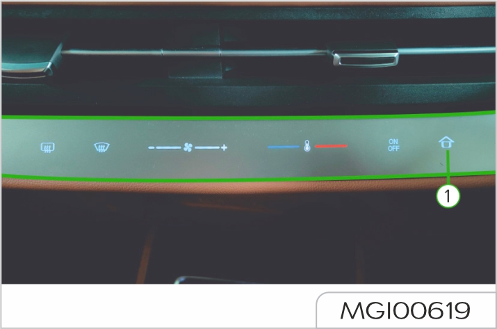
1. HOME Button
Short press the HOME button (1) to return to the HOME page from other interfaces; if the current page is the HOME page, this action is invalid.
Long press the HOME button (1) for about 10 seconds to restart the entertainment system.
For the user guide and help of the entertainment system, please follow the following steps to access the related application of the vehicle entertainment system.
As the entertainment system software will continue to be updated and iterated, the pictures in this manual are only schematic diagrams, which may be slightly different from this vehicle. They are for reference only, and the actual vehicle status shall prevail.
The use guide and help of the entertainment system are presented on the relevant pages of each function. The specific presentation is as follows:
Click icon
![]() to expand the
corresponding instructions for the
function. The specific style is as
follows:
to expand the
corresponding instructions for the
function. The specific style is as
follows:
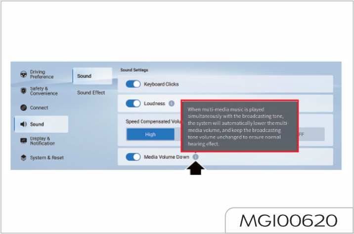
Light control switch
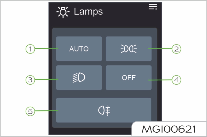
The light control switch is on the central control screen. Please operate it through the touch keys on the central control screen.
Click the lamp touch button, and the corresponding lamp will light up. The daytime running lights automatically illuminate after the vehicle is started
If headlights are on when the vehicle is parked, the battery will discharge, and the vehicle may be unable to restart due to battery lack of power. An audible warning will sound if the headlight switch is on when the vehicle is powered off. Before the vehicle is powered off, if the headlight control switch is in AUTO position, the headlight control switch is still in AUTO position after the vehicle is powered on again.
Before the vehicle is powered off, if the headlight control switch is not in AUTO position, the headlight control switch is in Light OFF position after the vehicle is powered on again.
See "Switches on steering column and steering wheel" in this section for more operation methods of turn signals and headlights.
Rear fog lights shall not be used until the visibility is obviously restricted (such as heavy fog or snow).
Daytime running light
Daytime running lights make it easier for others to see the front of your vehicle clearly during the day.
If your vehicle is equipped with daytime running lights, the daytime running lights will illuminate when the vehicle is powered on. The low beam, taillights, position lights, and other lights do not illuminate when the daytime running lights are on.
When the vehicle is powered off, the daytime running lights will go out. Comply with ECE R87 regulatory requirements for daytime running lights.
If your vehicle is configured with AFS, the system will automatically adjust the headlight leveling according to the vehicle speed, vehicle load and climbing capacity.
When the vehicle is carrying occupants or luggages, the headlight beam will be automatically adjusted upward or downward.
Headlight beam-focusing is extremely important for safe driving. In case of any failure in the AFS, please contact Our Service Dealer for service as soon as possible.
Press the hazard warning light switch to activate all the turn signals simultaneously, and the "direction indicator (green)" in the instrument cluster will illuminate and flash. Press the switch again to turn off the above lights.
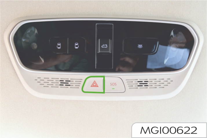
Turn on hazard warning lights to prompt other vehicles that your vehicle has a malfunction and approaching your vehicle may be dangerous.
In case of emergency, press the SOS E-call System switch, to send signals to monitoring platform, which carry out subsequent rescue work
This switch can be used to get any kind of information from Pulse-hub as well.
SOS Button need to be pressed for 3-5 Sec to trigger call.
If the network is available and the message is sent successfully, MG pulse hub will call in and message “E call in progress” will appear in the Screen and Cluster.
For disconnecting the call same button needs to be pressed for 3-5 Sec.
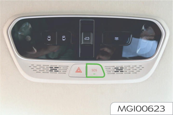
During “E-call in progress”, no function can be controlled from the Entertainment system.
This switch is for emergency use and to get information from Pulsehub, please operate when required.
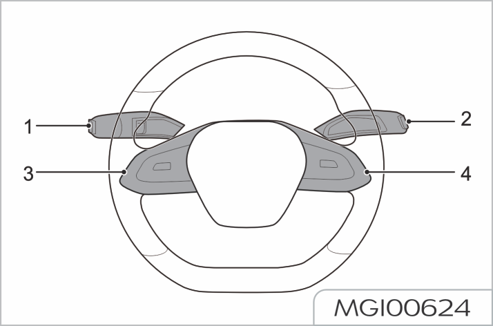
Front windshield wiper and washer
Type 1

Type 2

Rotate the lever switch to the desired position.
Position 1–HI: high-speed wipe.
Position 2–LO: low-speed wipe.
Position 3 (type 1)–INT: intermittent wipe.
Position 3 (type 2)–AUTO: automatic intermittent wipe. The rain sensor detects the rainfall on the windshield and automatically adjusts the wiping frequency of windshield wipers.
Always keep the rain sensor free of dust, dirt or ice.
Position 4–OFF: wiper of
Position 5–
![]() : Washers. Turn
the lever switch to the position. The
washer will operate immediately. After
a short interval, the wiper will operate
with the washer. The washer will be
off when the lever switch is released.
: Washers. Turn
the lever switch to the position. The
washer will operate immediately. After
a short interval, the wiper will operate
with the washer. The washer will be
off when the lever switch is released.
The wipers will continue to operate for 3 consecutive wipes after the lever switch is released, and operate for 1 wipe after 3 consecutive wipes.
Intermittent wipe/variable interval
Worn wiper blades may not clear the windshield properly, thus reducing forward visibility and resulting in accident. Always renew worn wiper blades immediately
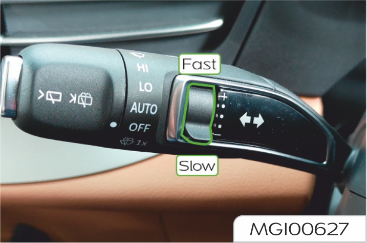
When the lever switch is in INT (intermittent wipe) (front windshield wiper and washer type 1) position, move the switch up and down to vary the interval between wipes.
When the lever switch is in AUTO (automatic intermittent wipe) (front windshield wiper and washer type 2) position, move the switch up and down to change the sensitivity of front wipers, and the rain sensor will adjust the wiping rate of front wipers.
In freezing or very hot conditions, to prevent damage to the wipers, ensure the blades are not frozen or otherwise adhering to the glass, and clear the screen of obstructions such as snow. Do not operate wipers when the windshield is dry. It can scratch the glass, cause the blades to wear prematurely and obscure vision.
Rear window wiper and washer
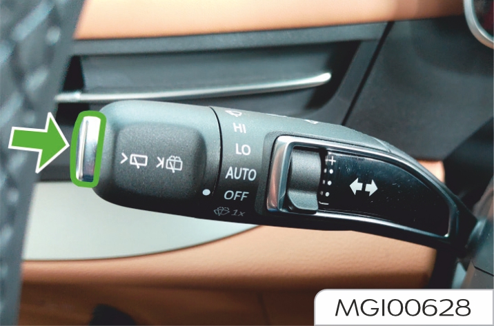
Short press the leftmost top of the wiper and washer lever switch, and the rear window wiper will operate.
Long press the leftmost top of the wiper and washer lever switch, the washer will spray water and the wipers will operate.
Turn signal lever switchq
Turn signals and direction indicators
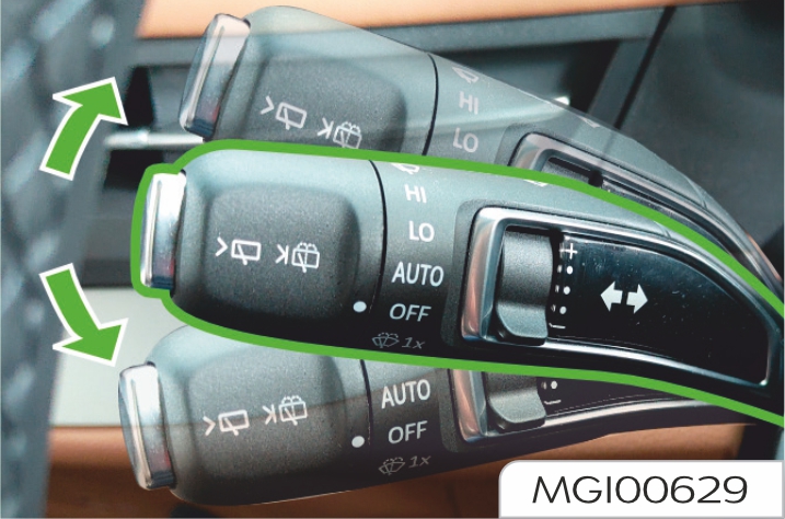
Right turn — push the lever switch upward.
Left turn — pull the lever switch downward.
The appropriate "direction indicators (green)" in the instrument cluster illuminate in time with the turn signals.
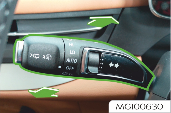
Push the lever switch away from the steering wheel, turn on the high beam, and at this time, the switch will automatically return to its original position; push the lever switch again away from the steering wheel, turn
off the high beam, and at this time, the switch will automatically return to its original position.
The "headlight high beam indicator (blue)" in the instrument cluster illuminates when the headlights are on high beam. To flash the headlights, slightly lift the lever switch intermittently towards the steering wheel.
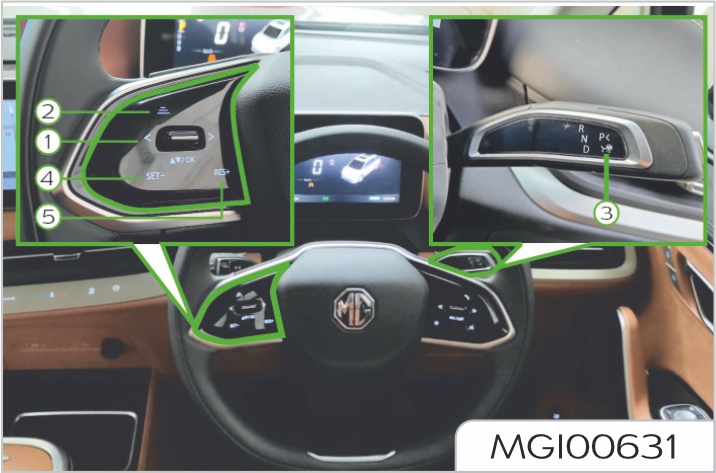
Position 1–
![]() : Instrument
cluster selection switch.
: Instrument
cluster selection switch.
Press upward, downward, leftward or rightward to page up, page down, page left or page right on the instrument cluster; press OK button to confirm your selection.
Position 2–
![]() : Settings of following
distance. Adjust the following distance
controlled by cruise function, and
press it once to switch the following
distance from Level 1 to Level 3
cyclically
: Settings of following
distance. Adjust the following distance
controlled by cruise function, and
press it once to switch the following
distance from Level 1 to Level 3
cyclically
ACC (Adaptive Cruise Control)
Position 3– : Adaptive cruise control switch. If the conditions are met, move the shift lever down to the bottom and release it to activate the ACC (Adaptive Cruise Control) function. To manually deactivate the cruise control, pull up the shift lever or shift the gear, and depress the brake pedal. See "ACC (Adaptive Cruise Control)" in the Starting and Driving section for more descriptions.
ICA (Integrated Cruise Assist)
Position 3– : Integrated cruise assist switch. If the conditions are met, move the shift lever down to the bottom twice and release it to activate the ICA (Integrated Cruise Assist) function.
To manually deactivate the cruise control, pull up the shift lever or shift the gear, and depress the brake pedal. See "ICA (Integrated Cruise Assist)" in the Starting and Driving section for more descriptions.
When the cruise control is activated:
Position 4– SET-: To decrease the cruise speed.
Position 5– RES+: To increase the cruise speed.
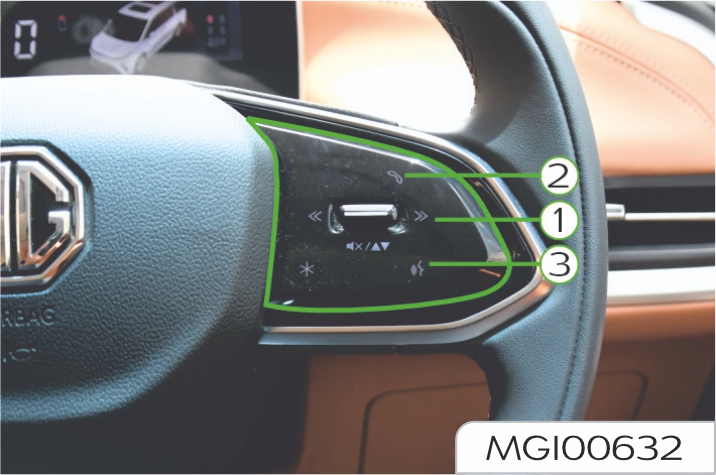
Position 1– : Volume control switch. Press upward to increase the volume and downward to decrease; long press to mute; short press , to switch to the previous band/MP3 track; long press to perform fast backward; short press to switch to the next band; long press to perform fast forward.
Position 2– : Bluetooth telephone switch. When Bluetooth is connected, this switch is the Bluetooth phone answering switch.In the general calling state: when there is an incoming call, short press the switch to answer, and long press it to hang up; during the call, short press the switch to hang up, and long press it also to hang up; during the dialing, short press the switch to hang up,
long press it also to hang up. During the call, if there is a call from a third party, short press the switch to hold the current call and answer the new call; long press it to hang up the new call and hold the original call. After the short-press, you can hang up the original call and answer the new call through the soft button on the central control screen.
Position 3– : Speech dialogue system switch. Press this switch to enable the speech recognition function; press again to disable the function.
Regardless of whether the vehicle is powered on or not, press the button, and the horn can work.
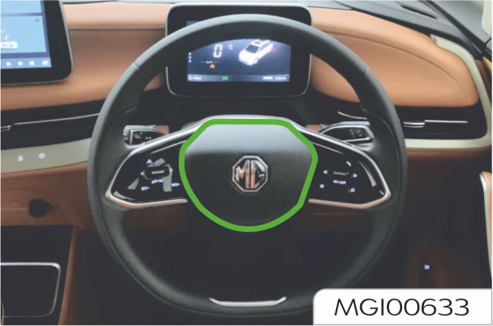
DEFECTIVE TYRES ARE DANGEROUS! Do NOT drive your vehicle if any tyre is excessively worn, damaged or inflated to an incorrect pressure. Do NOT overload vehicle.
Incorrect tyre inflation pressures or an unbalanced wheel and tyre assembly can seriously affect the stability, especially when driving with high payloads or at high speeds. Underinflation will increase rolling resistance and accelerate tyre wear, resulting in tyre damage, even an accident.
Always drive with consideration for the condition of the tyres; the most common causes of tyre failure are:
Uneven tread wear can be caused by faulty wheel alignment.
The vehicle speed shall not exceed the maximum allowable speed of the installed winter tyres, otherwise the tyres may suddenly lose pressure, delaminate, or even burst, which may easily cause accidents!
Be sure to adjust the speed according to the specific climate, roads and traffic conditions. Do not take risks by taking advantage of the anti-skid performance provided by winter tyres and beware accidents!
Winter tyres can improve the handling stability and braking performance of the vehicle when driving in a low temperature environment or on icy roads. It is suggested that winter tyres should be used when the temperature is lower than 70C.
When a vehicle is running under winter road conditions, winter tyres can greatly improve the handling stability and braking performance. Non-winter tyres have poor skid resistance at low temperatures or on icy roads due to their structure (tyre width, rubber composition, pattern type, etc.).
It is recommended to use winter tyres of the same size and load index as that of the original tyres, and all the four wheels shall use winter tyres.
When the tread depth of winter tyres is worn to 4mm, the skid resistance will decrease obviously.
The maximum allowable speed of winter tyres shall be subject to the speed code on the tyres.
| Speed symbol | Maximum speed (km/h) |
|---|---|
| C | 60 |
| D | 65 |
| E | 70 |
| F | 80 |
| G | 90 |
| J | 100 |
| K | 110 |
| L | 110 |
| M | 130 |
| N | 140 |
| P | 150 |
| Q | 160 |
| R | 170 |
| S | 180 |
| T | 190 |
| H | 210 |
| V | 240 |
| W | 270 |
| Y | 300 |
In addition, it is recommended to set the overspeed alarm, which can be controlled to turn on or off via the touch button on the center console screen.
When the temperature rises above 70C, it is recommended to replace winter tyres with non-winter tyres.
When driving a vehicle in the snow, it is recommended to apply S anti-skid chain to the driving wheels.
The anti-skid chain could increase the traction when driving on roads in winter. If you want to install the antiskid chain, please remember that:
It is just in the snow that you can drive the vehicle at maximum speed allowed by the anti-skid chain. Please comply with the regulatory requirements of the resident country. Remove the anti-skid chain immediately when driving on the snow-free road.
Each driver is obliged to ensure his vehicle is free of overload.
The maximum allowable total mass is indicated on the VIN Plate located at front lower of B pillar. This handbook introduces the correct vehicle weight parameters, see "Vehicle weight parameters".
Secure all loads in the vehicle to prevent personal injury due to movement of loads. The driver is obliged to ensure all goods have been fixed correctly.
There is a legal requirement to display a specific type of external warning sign on the vehicle if certain hazardous goods are being carried.
Manually unlock and lock the driver door
When the vehicle is powered off or the doors can not be unlocked or locked electronically, the driver door can be unlocked and locked manually.
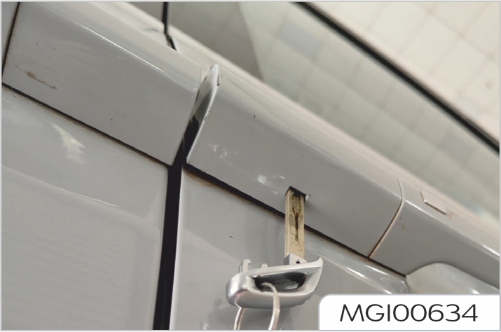
After unlocking and locking is completed, it is required to pull the exterior door handle first before mounting the cover.
Manually lock the front occupant door and rear doors
When the vehicle is powered off or the doors can not be locked
electronically, the front occupant door and rear doors can be locked manually
Use the key to turn the lever at the position shown counterclockwise, and then close the door to lock it.

To open the front occupant door and rear doors, pull the interior door handle twice to open the door.
Manually unlock the tailgate
When the vehicle is powered off or the tailgate can not be unlocked electronically, the tailgate can be unlocked manually.
Open the cover at the lower end of the tailgate inner trim panel and press down the white lever to open the tailgate.
Manual tailgate
Power tailgate
To close the tailgate, lower the tailgate and press it down firmly to make sure that the tailgate is locked securely.
When you encounter a problem during driving and have to stop the vehicle or slow down, you shall press the hazard warning light switch on the front roof vanity light, the "direction indicator (green)" on the instrument cluster will illuminate and flash, meanwhile all the turn signals flash to alert others and make the police know you are in trouble.
The warning triangle is placed in the front compartment storage box.
When you encounter a problem during driving and you have to pull the vehicle over, if the situation permits, on the conventional road, please place a warning triangle about 50 - 150m right behind the vehicle to alert vehicles behind; On highways, a warning triangle should be placed about 150m right behind the vehicle;
in rainy and foggy day with low visibility, place the warning triangle about 200m right behind the vehicle, to alert vehicles behind.
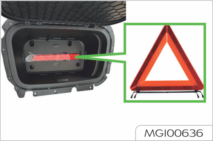
While towing or being towed, relative national regulations about vehicle towing shall be abided by
Front towing hitch
If this vehicle is to be towed from the front, first pry off the towing hitch cover from the lower part of the front grille, and screw the towing hitch placed in the vehicle tools to the front bumper.
After the vehicle towing is completed, unscrew the towing hitch and put it back in its original position, and then close the towing hitch cover.
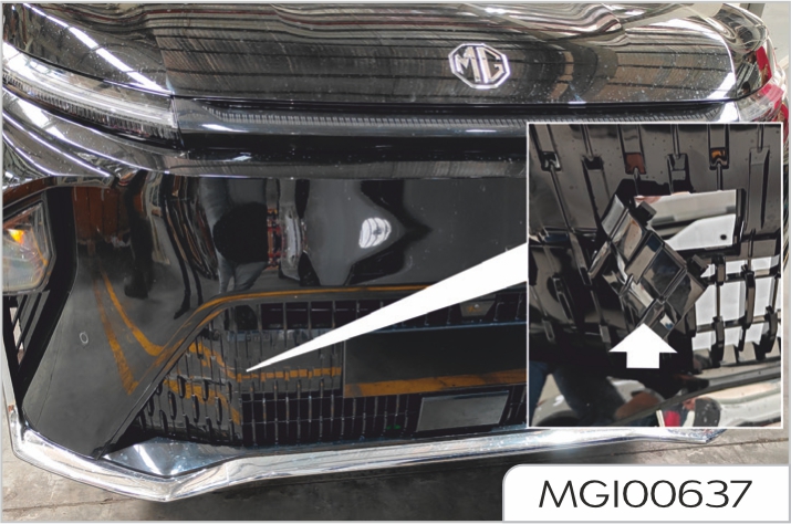
Rear towing hitch
It applies to vehicles configured with rear towing hitch.
If the vehicle is to be towed from the rear, first pry off the towing hitch cover from the left side of the rear bumper, and screw the towing hitch placed in the vehicle tools to the rear bumper.
After the vehicle towing is completed, unscrew the towing hitch and put it back in its original position, and then close the towing hitch cover.
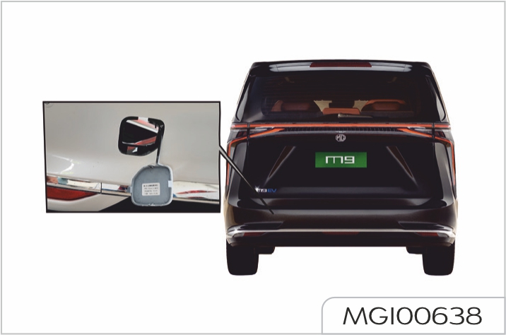
The maximum weight that the towing hitch can bear is the GVW. Do not tow a vehicle with a weight more than this value.
The application range of towing rope is as shown below:
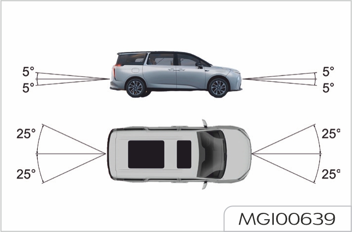
Before towed
To ensure the steering gear can rotate freely, be sure to power on the vehicle and keep it powered on during towing process. This is to ensure the steering is unlocked, and the turn signal lamps and brake lamps can operate.
Being towed
When the vehicle is being towed, release the parking brake and engage N gear.
There is no brake booster assist or power steering assist when the motor is not running. In this case, it requires greater effort to operate the brake pedal, and longer time and greater effort to rotate the steering wheel.
When towing a vehicle, be sure to lift its drive wheels off the ground, with the towing speed lower than 30km/h, the towing distance less than 50km, and the shift lever in N gear.
After a severe collision, if you find it impossible to move the shift lever into N, shift from P to another gear, or turn the steering wheel, please note that the drive wheels must not be on the ground when towing. Failure to do so may lead to severe damage to the transmission and high service costs. It is recommended to tow the vehicle with a flatbed trailer. When towing, all four wheels must be off the ground.
Recommended vehicle towing
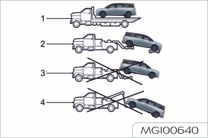
When the vehicle is pulled onto the flatbed trailer, it is prohibited to have any person or object behind the trailer, as this may lead to personal injury or death.
When towing the vehicle with the front wheels lifted or on a flatbed trailer, passengers are not allowed to stay in the vehicle, otherwise an accident may occur and lead to personal injury or death.
Always wear protective gloves and eye protecting glasses when working on a battery. Do not use naked light, cause sparks or smoke in the area of the battery. You can be seriously injured and the vehicle damaged.
To disconnect battery, disconnect negative (-) earth terminal first and then positive (+). To connect battery, install and secure positive cable (+) first and then negative (-) cable. Smear the terminals with petroleum jelly
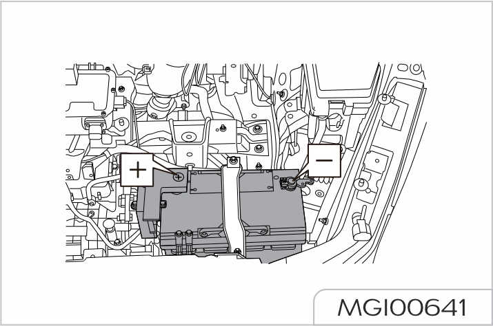
Before disconnecting the battery, always shut down the motor and all electrical devices for more than 2 minutes.
While disconnecting, never allow the terminal to contact with the metal parts of vehicle body. Otherwise short circuit may cause electric spark. Electrical system will be damaged if positive and negative cables are connected reversely
Never pull or tow the vehicle to start.
Ensure the rated voltage of two batteries is the same (12V) and the jumper cable is acknowledged as the cable used for 12V vehicle battery.
Jumper

Starting
Start the battery-powered vehicle to be powered and allow it to idle for several minutes.
If it fails to start after several attempts, the vehicle may need maintenance.
If the malfunction indicator lamp appears on the instrument cluster after starting up the vehicle, it may be due to low battery voltage. Please try to power off and power on the vehicle after the battery voltage is stable (the vehicle can be started on its own without jump start). If the malfunction indicator lamp on the vehicle’s instrument cluster remains on after several attempts, the vehicle is likely to need repairing. Please contact our Service Dealer for repair.
Disconnecting
Regular maintenance is the key to economy, safety and reliability for your vehicle and it must be remembered that the responsibility for maintaining your vehicle in a safe, roadworthy condition rests ultimately on you, the owner/operator.
Necessary maintenance and the intervals have been specified to maintain your vehicle properly. Regular vehicle maintenance shall be done by Our Service Dealer in accordance with Warranty & Service Handbook.
It is in your best interest to have your vehicle regularly maintained in accordance with regulations.
Our Service Dealers are recommended as they have qualified personnel, required facilities and can offer the unique pre-planned service which will give maximum vehicle reliability
The following are a few simple but important checks which you shall make at regular intervals before driving to ensure reliable and economic operation:
Daily checks
Weekly checks or check before a long journey
-Coolant
- Windshield washer fluid
- Brake fluid
Harsh conditions
For vehicles often used in harsh conditions, it is recommended to shorten the maintenance interval.
Regular vehicle maintenance shall be done by Our Service Dealer in accordance with Warranty & Service Handbook.
Open front compartment hood
In the direction as shown in the figure, pull up twice the unlock handle of front compartment hood below the instrument desk on the driver side to unlock the front compartment, and lift the front compartment hood.
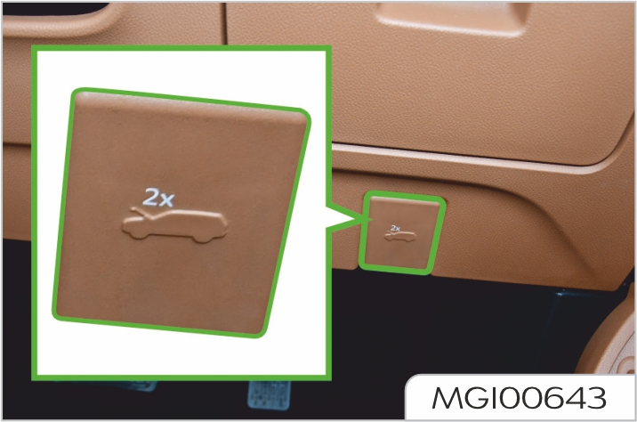
Close front compartment hood
Hold the front compartment hood with both hands and then lower it. When the front compartment hood is lowered about 20-30 cm away from its locking position, apply a certain downward force to close it with certain acceleration.
After closing the front compartment hood, check if it is completely locked by trying to lift its front edge. If the front compartment hood is not completely locked, please open it again and repeat the closing action.
Before closing, check that there is no tools, rags, equipment, etc. left in the area under the front compartment hood.
Front compartment hood unclosed alarm
If the front compartment hood has not been locked completely, the corresponding alarm icon will be displayed on the screen.
If the front compartment hood is found not locked completely when the vehicle is running, then warning tones will be sounded together.
Coolant is harmful if swallowed. Do not allow coolant to contact the eyes or skin. If it does, rinse immediately with plenty of water.
Please add correct specification coolant. Never driving the vehicle if coolant of correct specification is not filled. Coolant specification see "Recommended fluid oil"
At specified intervals the cooling system shall be drained, flushed and refilled with the correct amount of coolant.
IndicaWhen refilling or replacing coolant, only the specified coolant can be used. The use of nonrecommended coolant could cause damage to the cooling system and may invalidate the warrantyes
Check and refill
Do not remove the expansion tank cap while the cooling system is hot, for overflowed water vapor or hot coolant may cause personal injury. If coolant has to be charged when the system is hot, wait for 10 minutes, place a thick cloth over the filler cap and turn the cap slowly anti-clockwise to release the pressure in the expansion tank before removing the cap.
Always check the coolant level with the vehicle on level ground and the coolant system stationary (cold condition).
The level is visible in coolant expansion tank and normal level shall be between "MAX" and "MIN" marks.
If the level drops to "MIN" mark, clean area around the coolant expansion tank cap and then turn anti-clockwise to remove it.
Top-up with the specified fluid between "MAX" and "MIN" marks.
Install the expansion tank cap
The coolant may expand when it becomes hot, so the liquid level may be higher than the level mark.
If the level has fallen appreciably, or topping-up is required frequently, suspect leakage or overheating and contact Our Service Dealer for inspection.
Battery circulation coolant reservoir
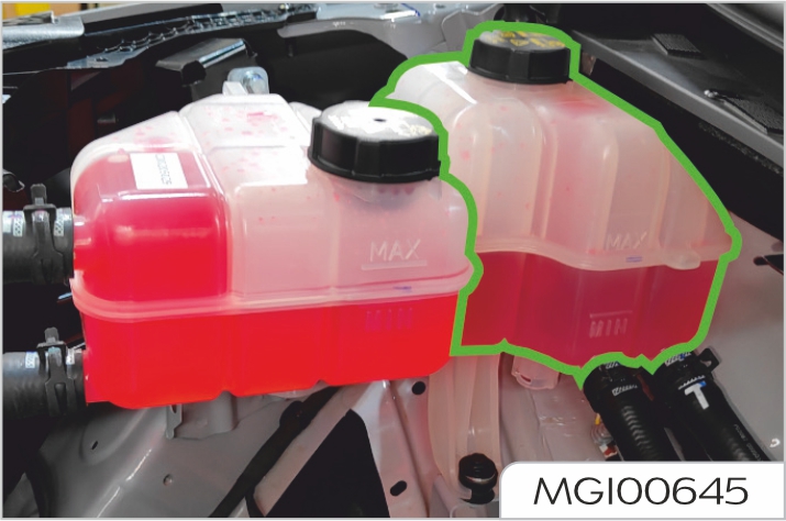
Electric drive system coolant reservoir
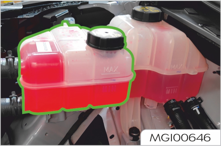
Precautions for cold weather
In order to reduce possible problems which may occur in cold weather, please consider the following suggestions:
If there is a significant drop in the level of the brake fluid, contact Our Service Dealer for service as soon as possible.
Use only new brake fluid of the specified type. Use of brake fluid which is old or not the specified type can cause loss of braking performance.
Brake fluid cleanliness is essential. Any dirt entering the system can cause loss of braking performance.
Do not allow brake fluid to contact your skin or eyes; If it does, rinse immediately with plenty of water. Keep brake fluid out of the reach of children.
Check and refill
Be sure to check the brake fluid level after the vehicle is parked on a flat ground and the brake system is in cold state. The "MAX" level mark is on the small reservoir, the "MIN" level mark is on the reservoir of the vacuum booster, and the normal level shall be between "MAX" and "MIN" marks. If the level drops to "MIN" mark, clean area around the filler cap and then turn anti-clockwise to remove it. Fill up specified new brake fluid between "MAX" and "MIN" marks and install the reservoir cap.

If the level falls below "MIN" mark, "brake system warning light (red)" on information cluster will light on. This indicates fault in the braking system which must be investigated immediately. If in driving, IMMEDIATELY bring the vehicle carefully to a halt. Contact Our Service Dealer for service as soon as possible. Do NOT continue driving.
Never discard used brake fluid casually to avoid the environment pollution.
Check and refill
Driving with a non-operational washer system can be dangerous; always check it before driving. When refilling the washer fluid, do not let it splash onto the paint surface of body. If the washer fluid splashes onto hands or other parts of human body, immediately wash it clean with clear water.
Washer fluid is used to clean the windshield. Check the level of the water fluid on a weekly basis. When the level is too low, please refill the washer fluid. To refill the washer fluid, please open the front compartment hood, open the washer fluid reservoir lid, and then close the lid tightly after refill. For washer fluid specification please see “Recommended fluid oil” in General Technical Parameters section.
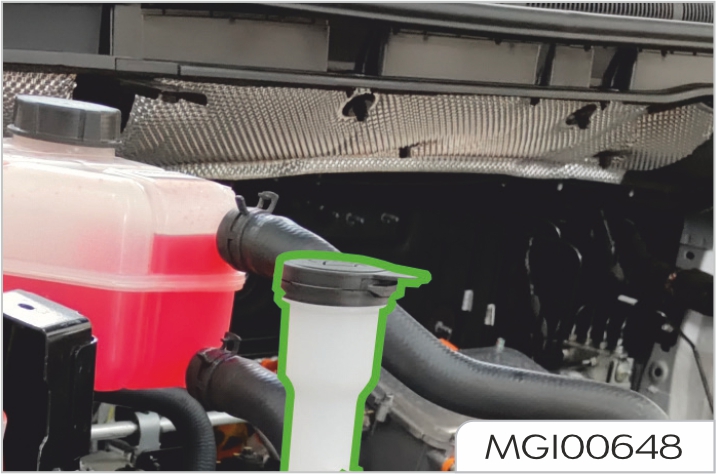
Washer nozzle
Check if the washer nozzle is clean and the direction is correct with the washer regularly. If the nozzle is blocked, insert a needle or thin wire into the hole to clear the blockage.
Inspection
Examine the edge of the blade for roughness or damage, and check that the blade rubber is secure throughout its length.
Traces of grease and other impurities on the rubber can prevent the wipers from working correctly, and can also damage the windshield.
Replacement of front windshield wiper blade

Adjust the front wiper switch to the maintenance function before replacing the front wiper blade.
Within 10 seconds after the vehicle is powered off, move the front wiper switch from OFF position to high speed HI position, and return it to the OFF position, to enable the front wiper blade move to the highest point (maintenance position), lift the wiper arm from the windshield to keep
the blade and arm at a angle of 15°, then replace the blade. The steps as follows:
Within a ignition cycle (vehicle powered off → vehicle powered on or started → vehicle powered off), use the front wiper maintenance function only once.
Replacement of rear windshield wiper blade

Maintenance and service
Wash with high-quality cleaner or neutral detergent and wipe it
clean with a dry, soft cloth that is free of lint.
Inspection
The belts also have a sensitive retractor which is designed to lock only during heavy acceleration, deceleration or sharp turns.
Do not test the locking device by deliberately jerking forward your upper body.
Check ALL seat belts as follows:
Maintenance and service
Do not attempt to repair the retractor or buckle mechanisms, or to modify the seat belts in any way. Seat belts subjected to strain as a result of an accident shall be replaced, and the anchorage points checked, by Our Service Dealer.
Regularly inspect the belt webbing for signs of abrasion or wear, paying particular attention to the anchorage points and adjusters.
Clean the seat belt with a sponge dipped with warm water and mild soap; it can be naturally dried, and must not be dried by direct heating or exposure under sunlight. Do not allow water to penetrate into the retractor. Never bleach or dye a seat belt as its strength may be reduced.
Fuses of this vehicle are located in three boxes.
Spillage of liquid to any electric components in the vehicle may damage the components, so it is required to cover any electric components. The content of the fuse specification list will be constantly updated according to the vehicle configuration and technical status, please see actual state of your vehicle. The corresponding components are provided only when the actual vehicle is configured with the functions. Otherwise, the components are not provided.
Driver compartment fuse box
Driver compartment fuse box is located behind the lower storage box at driver side.
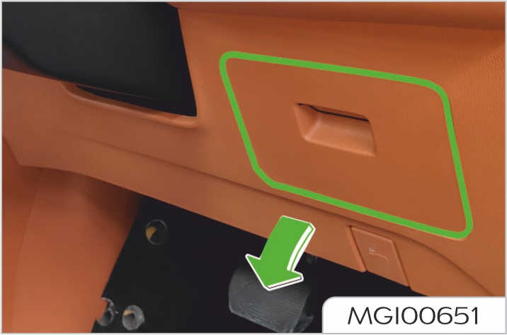
Fuses in the driver compartment fuse box can be identified by the label on the back of lower storage box cover at driver side.
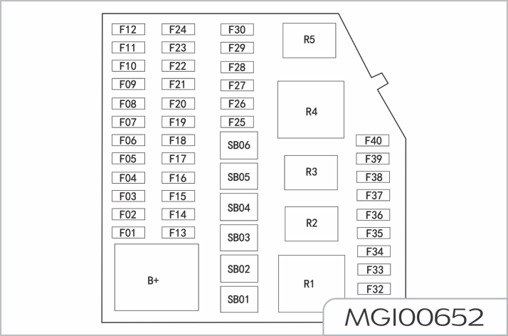
| Code | Specification | Function |
|---|---|---|
| F01 | 10A | A/C control module / ETC / driver monitoring camera / rear A/C panel / traveling data recorder |
| F02 | 7.5A | Combined switch - Electronic shift lever |
| F03 | 7.5A | Automatic anti-dazzle interior rearview mirrors / stream media rearview mirrors |
| F04 | 7.5A | HUD (Head-up Display) / instrument cluster |
| F05 | 10A | ICGM (intelligent gateway) |
| F06 | 7.5A | Front high voltage PTC |
| F07 | 10A | ADU (driving domain control unit) / ADC (camera) / ADAS (driver assistance system) |
| F08 | 15A | Steering wheel heating KL15 power |
| F09 | 7.5A | PM2.5 / ambient light sensor / roof vanity light / roof atmosphere light / sunvisor light |
| F10 | 7.5A | Central control switch / steering wheel / electric concealed outlet / driver (front passenger) flagship and luxury headrest accessory / driver (front passenger) flagship and luxury front passenger heating pad and headrest accessory |
| F11 | 7.5A | HUD (Head-up Display) |
| F12 | 10A | Single 12.3-inch display / front passenger entertainment screen / front passenger small screen |
| F13 | 25A | Entertainment mainframe power supply |
| F14 | 30A | Third-row left high-end seat |
| F15 | 30A | Third-row right high-end seat |
| F16 | 10A | Rear A/C panel / A/C control module |
| F17 | 10A | IBDU (intelligent body domain controller module) (exterior lamp) KL30 power 2 |
| F18 | 7.5A | Combined switch - right shift lever |
| F19 | 20A | 220V inverter |
| F20 | 10A | ICGM (intelligent gateway) |
| F21 | 10A | OBD commissioning / diagnosis /calibration |
| F22 | 10A | Light & rain sensor |
| F23 | 7.5A | ADAS/ADC/AVM |
| F24 | 10A | Instrument cluster |
| F25 | 25A | Power amplifier |
| F26 | 30A | Front passenger flagship and luxury memory module, and massage and lumbar support |
| F27 | 10A | BMS |
| F28 | 7.5A | ADU (driving domain control unit) |
| F29 | 10A | Integrated tri-screen |
| F30 | 30A | third-row right high-end / low-end VIP seat |
| F31 | / | Reserved |
| F32 | / | Reserved |
| F33 | / | Reserved |
| F34 | / | Reserved |
| F35 | / | Reserved |
| F36 | 20A | Front sunroof |
| F37 | 10A | Transportation mode relay |
| F38 | / | Reserved |
| F39 | / | Reserved |
| F40 | 10A | Power rearview mirror heating power |
| SB01 | 40A | Front blower motor |
| SB02 | 40A | Rear windshield / power rearview mirror heating power |
| SB03 | 30A | Front passenger power window regulator power |
| SB04 | 30A | Rear blower relay / rear blower power |
| SB05 | 30A | PTC1 |
| SB06 | 30A | PTC2 |
| R1 | 40A | Front Blower Relay |
| R2 | 35A | PTC1 Relay |
| R3 | 35A | Rear Blower Relay |
| R4 | 40A | Defrost Relay |
| R5 | 35A | PTC2 Relay |
Front compartment fuse box
Front compartment fuse box is located at the right of compartment wall at the front hood bottom (viewed from the front of vehicle). Fuse can be accessed by just removing the cover of front compartment fuse box.
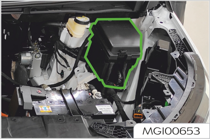
Before opening the fuse box cover, make sure its surroundings are dry and no fluid flows from any direction into the opened fuse box, otherwise the fuse box will be damaged, leading to serious consequences.
Fuses in the front compartment fuse box can be identified by the label printed at the back of the fuse box cover.
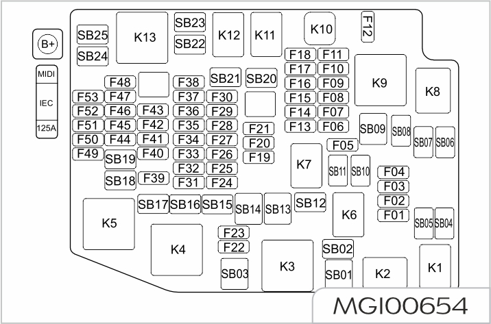
| Code | Specification | Function |
|---|---|---|
| SB01 | / | Reserved |
| SB02 | 30A | Front wiper |
| SB03 | / | Reserved |
| SB04 | 30A | Rear sunroof |
| SB05 | 30A | Front sunroof / electric tailgate ECU KL30 transportation mode power |
| SB06 | / | Reserved |
| SB07 | / | Reserved |
| SB08 | 30A | Right electric power side load door KL30 |
| SB09 | 40A | Trailer ECU |
| SB10 | 30A | Power driver seat KL30 |
| SB11 | / | Reserved |
| SB12 | / | Reserved |
| SB13 | 60A | IBOOST (electric vacuum booster) KL30 |
| SB14 | 60A | ESC motor KL30 |
| SB15 | 25A | Trailer |
| SB16 | 30AIEC | (driver compartment fuse box) KL15 |
| SB17 | 30A | Left electric power side load door KL30 |
| SB18 | 30A | IEC (driver compartment fuse box) KL30 |
| SB19 | 30A | Second-row left power seat KL30 |
| SB20 | / | Reserved |
| SB21 | 30A | Left window regulator |
| SB22 | / | Reserved |
| SB23 | 30A | Power tailgate ECU KL30 |
| SB24 | 40A | ESC solenoid valve KL30 |
| SB25 | / | Reserved |
| F01 | 20A | Reserved |
| F02 | 15A | IBDU (intelligent body domain controller module) (washer motor) KL30 |
| F03 | 3A | UEC (front compartment fuse box) GND 3 |
| F04 | 15A | Horn |
| F06 | / | Reserved |
| F07 | 10A | Intelligent grille / cooling fan KL87 |
| F08 | / | Reserved |
| F09 | / | Reserved |
| F10 | / | Reserved |
| F11 | / | Reserved |
| F12 | / | Reserved |
| F13 | / | Reserved |
| F14 | 20A | BMS electronic water pump |
| F15 | / | Reserved |
| F16 | 20A | Ignition coil/cooling water pump |
| F17 | / | Reserved |
| F18 | / | Reserved |
| F19 | 20A | IBDU (exterior lamp) KL30 power 1 |
| F20 | 10A | Airbag module KL30 |
| F21 | 10A | EMS (engine control module) KL30 |
| F22 | 25A | IBDU (door lock) |
| F23 | 25A | Nets-within-nets ECU KL30 |
| F24 | 25A | Second-row power seat KL15 |
| F25 | 10A | EMS (engine control module) / IMCU (motor and vehicle control unit) KL15 |
| F26 | 7.5A | EPS KL15 |
| F27 | 10A | Transmission TCU / PTC / low speed alarm KL15 |
| F28 | b10A | ADC (camera) / high precision inertial navigation / front millimeter-wave radar KL15 |
| F29 | 10A | Airbag module KL15 |
| F30 | / | Reserved |
| F31 | 20A | Transmission TCU / EPP drive motor / IMCU (motor and vehicle control unit) KL30 |
| F32 | 15A | Third-row left power seat KL15 |
| F33 | 15A | Third-row right power seat KL15 |
| F34 | 15A | Power driver seat KL15 |
| F35 | 10A | ESC/IBOOST/AVM KL15 |
| F36 | 10A | Nets-within-nets ECU / power amplifier / OMS KL15 |
| F37 | / | Reserved |
| F38 | / | Reserved |
| F39 | 20A | IBDU (exterior lamp) KL30 power 4 |
| F40 | 20A | IBDU (exterior lamp) KL30 power 3 |
| F41 | 10A | Electric power side load door / lane change assist / high precision inertial navigation / kick sensor KL30 |
| F42 | 15A | ADC (camera) KL30 |
| F43 | 10A | PO DCDC / PO BMS / PO motor / CCU (combined charging unit assembly) / EVCC (electric vehicle communication controller) KL30 |
| F44 | / | Reserved |
| F45 | 7.5A | Wireless charging / door atmosphere light / driver window regulator KL30 power |
| F46 | 7.5A | Rearview camera / HUB (video gateway) / rear millimeter-wave radar KL30 power |
| F47 | 20A | Front 12V power |
| F48 | 20A | Second-row power seat USB KLR |
| F49 | 15A | Rear wiper |
| F50 | 7.5A | 220V inverter / front USB / roof USB KLR |
| F51 | 15Ab | Rear seat 12V power |
| F52 | / | Reserved |
| F53 | 7.5A | Rear side USB / second-row right seat USB / window regulator switch KLR |
| MIDI | 125A | ICE (driver compartment fuse box) KL30 |
| K1 | / | Front wiper high-low speed relay |
| K2 | / | Front wiper control relay |
| K3 | / | Reserved |
| K4 | / | IG relay |
| K5 | / | Power-saving relay |
| K6 | / | Reserved |
| K7 | / | Reserved |
| K8 | / | Reserved |
| K9 | / | Main relay |
| K10 | / | Reserved |
| K11 | / | Reserved |
| K12 | / | Reserved |
| K13 | / | ACC relay |
Battery fuse box
The battery fuse box is located on the battery positive terminal.
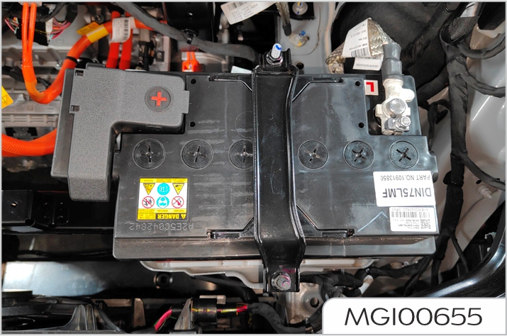
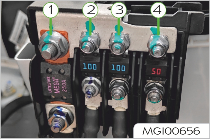
| Code | Specification | Function |
|---|---|---|
| 1 | 250A | Front compartment fuse box KL30 power |
| 2 | 100A | EPS KL30 power |
| 3 | 100A | Rear PTC heating KL30 power |
| 4 | 50A | Cooling fan KL30 power |
Fuse replacement
Only replace with fuses of the same specifications/rated current. Installing nonspecific fuse will damage electrical system and even cause fire. Before attempting to replace the fuse, the vehicle power and all electrical devices must be turned off. Any unauthorized change to vehicle electrical system will cause serious adverse effect and fire on the electronic management system.
Pull the fuse outward with puller provided in fuse box to remove the fuse. Internal wiring of the fuse can be used to identify blown fuse (arrowed).
Repeated failure with the same fuse is the indication of circuit failure. Please contact Our Service Dealer as soon as possible.
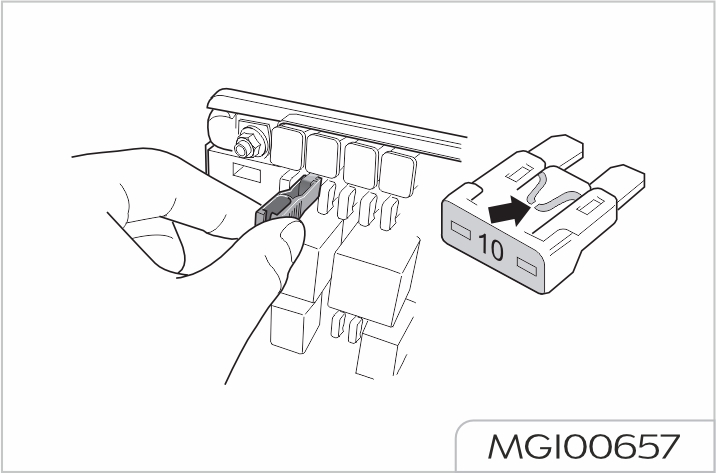
Unauthorized change to electrical system of the vehicle will invalidate the warranty
Warnings and instructions for battery: Wear goggles!
The battery acid is strongly corrosive. Ensure to wear protective gloves and goggles!
Open fires, electric sparks, strong lights and smoking are strictly prohibited!
Explosive gas mixture may be generated during battery recharging!
Ensure to keep any child away from the acid and the battery!
There may be risks of injury, corrosion, accident and fire during operations on the battery and any electrical appliance in the vehicle!
Ensure to wear goggles. Do not allow acid or leaded particles to get into your eyes or onto your skin or clothes.
The acid in the battery is highly corrosive. Ensure to wear protective gloves and goggles.
The battery cannot be turned over, or acid may flow out of the vent. If acid gets into your eyes, immediately rinse with clean water for a few minutes, then see a doctor immediately. If acid splashes onto your skin or clothes, immediately neutralize it with thick soap solution, and then rinse with plenty of water. If you drink acid by mistake, see a doctor immediately.
Open fires, electric sparks, strong lights and smoking are prohibited. When working on cables and electrical appliances and removing electrostatic loads, avoid the generation of electrical sparks. The electrodes of battery can NEVER be short-circuited, or it may cause personal injury due to large energy sparks.
Explosive gas mixture may be generated during battery recharging. The gas vent of battery should be kept unblocked to discharge the gas correctly.
During recharging, the battery should be located in a space with good ventilation.
Ensure to keep any child away from the acid and the battery
Turn off the motor, vehicle power supply and all electrical appliances before working on electrical appliances. Remove the negative cable of battery.
When replacing bulbs, only the lights are required to be turned off.
Pay attention to the polarities of power supply. Before powering on, the matches of polarities must be checked.
The duration of each powering on should not be less than 5 seconds. Try to avoid powering on and off too frequently.
When removing the battery, please remove the negative cable before positive cable. Before powering on the battery again, all electric appliances should be turned off. First connect the positive cable, then the negative one. Never connect the cables incorrectly - risk of fire!
Unauthorized removal and installation of battery is strictly prohibited since such operation may cause severe damage to the battery and fuse box in some cases. Please contact Our Service Dealer.
Do not disconnect the battery when the vehicle is powered on or the motor is running, otherwise it may damage the electrical appliances (electrical components).
To prevent the battery housing from exposing to ultraviolet ray, do not expose the battery under the sunshine.
Duration of storing the vehicle
If the vehicle is to be parked for an extended period of time, the static current electrical appliance (like clock, security devices) will drain the battery, and the battery has to be charged. To avoid such case, charge the battery or disconnect the battery negative cable during the vehicle parking.
Please pay attention to the warnings & instructions for battery before working on it.
Ensure to turn off the vehicle power supply during parking, otherwise the parking time can be reduced significantly
Operating in winter
There are particularly strict requirements on the vehicle battery operation in winter. In addition, the starting power provided by the battery at low temperature is only a part of that at normal temperature. Therefore, we recommend to have the vehicle battery checked by Our Service Dealer before the cold season begins, and recharge it if necessary.
If the vehicle is not used for weeks in cold season, please remove the vehicle battery and store in an ice-free room, to prevent it from freezing and damage.
Charging the battery with ground equipment
Do not charge any frozen battery, there is a risk of explosion! Even if the battery has been unfrozen, there may be battery acid spilling out and cause corrosion. Any frozen battery must be replaced.
Turn off the vehicle power supply and all electrical appliances before charging. If the vehicle has been parked for a long period and cannot be started due to lack of power (general terminal voltage≤12V), the battery must be removed from the vehicle and charged with a ground equipment (follow the instructions provided by the manufacturer of the charging equipment).
During charging with small current (e.g., a small charging equipment), it is unnecessary to remove the connecting cables of battery. However, please ensure to read the instructions from the manufacturer of the charging equipment.
Before fast charging (i.e., large current charging), both of the connecting cables must be removed.
Please pay attention to the warnings & instructions for battery before working on it. During the charging, the charging equipment can only be powered on after the electrode clamps of charging equipment is connected to the electrodes of battery as required. After the charging is finished, turn off the charging equipment first, remove the power cable, and then remove the electrode clamps of charging equipment from the battery. When charging the external device, the electrodes must be connected accordingly. Do not connect the positive electrode of the battery to the negative electrode of the charging device, and do not connect the electrodes in reverse. Such operation will cause serious damage to the DCDC converter, resulting in failure for vehicle to drive, please contact Our Service Dealer.
Removing the battery
Turn off the vehicle power supply and all electrical appliances before the battery removal. To remove the battery, firstly remove the negative cable and then the positive cable. And then remove the bolt on the mounting bracket of battery to remove the battery
Replacing the battery
The battery installed on your vehicle is designed for the corresponding mounting location. To replace the battery, please ensure to use one with the same voltage (12V), structure and safety label. The current strength and capacity should be same with the original battery. Our Service Dealer can offer you with genuine batteries.
When installing the battery, please ensure that the vehicle power supply is turned off and all electric appliances are turned of
Concerning the disposal of used battery, it is suggested to have the battery replaced by Our Service Dealer. Additionally, the battery can never be treated as household garbage because it contains sulfuric acid and lead.
Installing the battery
Before installing the battery, turn off the vehicle power supply and all electrical appliances. Put the battery in the installation position prepared for it, and fix it with the battery bracket. When connecting the battery, please fix the positive cable before the negative cable.
To prevent the battery from discharging, please turn off the vehicle power supply when you leave the vehicle.
Instructions and restricted conditions
According to the characteristics of the lithium battery, the vehicle must be charged and discharged every 30 days in storage period, a long time parking easily results in damage of battery, thereby affects the running of whole vehicle. Failure to do so may result in loss or damage of the power battery, may affect your enjoyment of the free warranty!
The electric vehicle model is different from the conventional vehicle, therefore it has particularity on aspects of operation, storage and maintenance, and now some cautions are informed to you.
DEFECTIVE TYRES ARE DANGEROUS! Do NOT drive your vehicle if any tyre is excessively worn, damaged or inflated to an incorrect pressure.
Frequently inspect the tyres and sidewalls for any sign of distortion (bulges), cuts or wear. Gravels and other sharp objects should be removed with a suitable blunt tool. If neglected, they may work through the tyre.
Tyre pressure
Driving with incorrectly inflated tyres can affect vehicle stability, increase rolling resistance, and cause rapid tyre wear and possible permanent damage to the cords of the tyre casing.
Remember tyre wear and inflation pressure regulations. It is the driver's responsibility to ensure that the tyres meet these requirements.
Please check the tyre pressure weekly, and adjust the tyre pressure according to the requirements on the tyre pressure identification at the front lower part of vehicle B-pillar. This Handbook introduces the correct tyre pressure in cold condition, see "Wheel and tyre" in General Technical Parameters section.
Pressure should be checked with an accurate Tyre Pressure Gauge when the tyre is cold instead of decreasing the value under warm condition as the pressure will be higher than normal pressure due to temperature. Be sure to install the valve caps to prevent dirt entry into the valve mechanism. A natural pressure loss will occur with time; any unusual pressure loss should be investigated and rectified.
Specified pressure applies to a cold tyre, while the pressure of hot tyre should be higher.
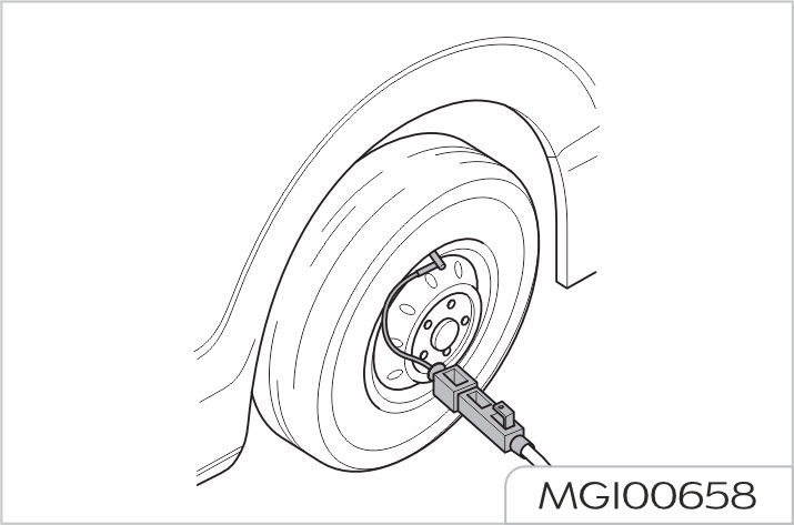
Wear indicator
There are wear indicators in the tread of all original tyres. When the tyre has worn down until 1.6 mm of the tread is remaining the wear indicators will appear across the full width of the tread pattern.
A tyre should be replaced immediately where any part of the wear indicator becomes visible. However it is in your interest to note that tyre safety and performance tends to reduce before the legal limit is reached. For example, badly worn tyres will increase the risk of aquaplaning.
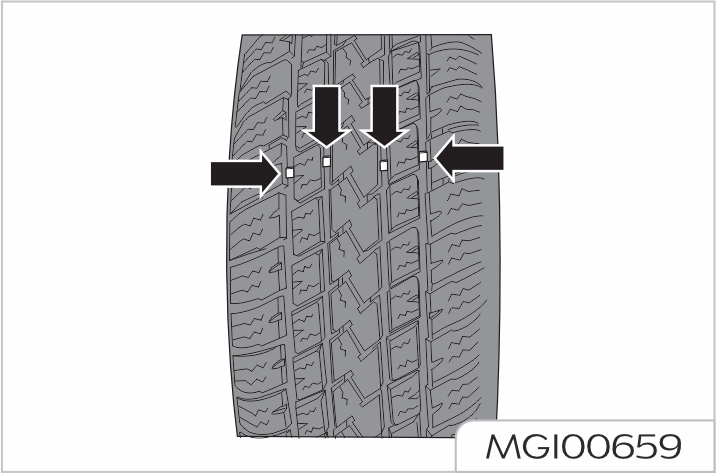
Tyre check and rotation
In order to achieve even tyre wear, it is recommended to check the tyres every 5,000km, and check the wheel alignment parameters under the curb weight of the enire vehicle as required. If irregular wear is found, the tyres position should be changed, and wheel alignment adjustments should be made if necessary. During the tyre rotation, check the tyres for correct dynamic balance.
During the tyre rotation, check for uneven wear and damage. Abnormal wear is usually caused by incorrect tyre pressure, poor wheel alignment, poor wheel dynamic balance, emergency braking or cornering. Check the tread or the side of the tyre for collision damage or bulges. If one of these conditions is found, the tyre shall be replaced. If fabric or cord is visible, the tyre shall also be replaced. After tyre disassembly and replacement, the inflation pressure of the front and rear tyres should be adjusted according to the tyre pressure label on the vehicle, and the wheel nut torque should be retested in the tightening direction to ensure it meets 180N·m±30%. If it does not meet the requirements, it needs to be tightened again.
Tyre rotation method
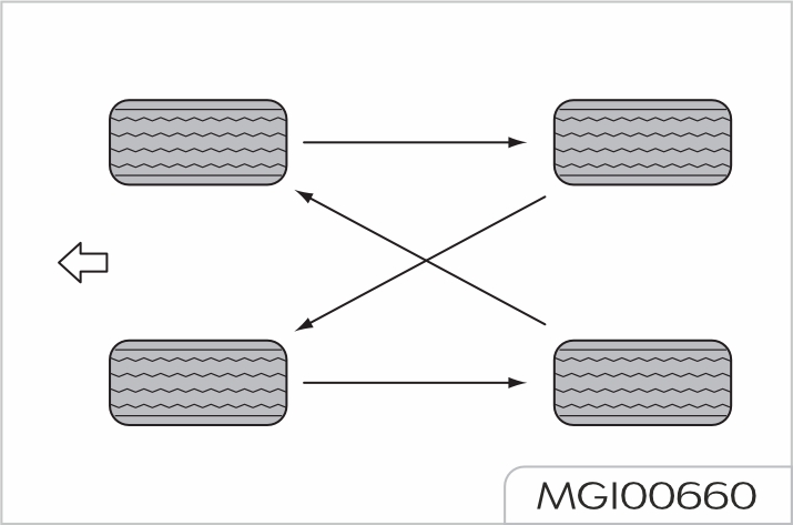
Vehicle wash
When driving for the first time after washing the vehicle, gently depress the brake pedal several times to remove moisture from the brake discs. Carefully wash the tyres. Never use a high pressure nozzle as it may damage tyres. If any damage is found, replace the tyre.
Water flushing is prohibited in the front part of the interior (near the dashboard area) to avoid unnecessary damage to related parts.
Do not flush the front compartment, battery compartment and peripheral inserts with water.
Careful attention to the following will help to retain the value of your vehicle:
Please timely remove the substances on the surface of the paint which seem harmless but in fact corrosive, such as bird droppings, resin, insect wreckage, tar spots, road salt and industrial dust. Otherwise permanent staining or damage will be produced.
Anti-corrosion of underbody
The underbody of your vehicle has been treated with anticorrosion. Check underbody anti-corrosion regularly
Use a water jet to remove accumulations of caked mud or debris on underbody. Especially in winter, when salt is used on icy and snowy roads.
Seat and trim
Often use vacuum sweeper or soft brush to clean dirt and dust accumulated on fibers. Often use clean cloth to wipe the trim. Use special cleaner to remove general trim dust, staining or spots. Use special cleaner to clean leather parts.
Door seals
To prevent rubber door seals from freezing in a cold weather, a rubber maintenance product or a silicone spray shall be used for its protection.
Window glass
Often use glass cleaner to clean window glass. Use high-quality cleaner or neutral detergent rather than abrasives or chemical solvents to wash.
Exterior trimming
Do not use chemical solvents to wipe, especially avoid using reagents containing benzene and naphtha solvents.
| Model | EPX1A-1200 |
|---|---|
| Drive mode | Front-motor, front-wheel-drive |
| Length, mm | 5270 |
| Width, mm | 2000 |
| Height, mm | 1840 |
| Wheelbase, mm | 3200 |
| Front/Rear overhang, mm | 955/1115 |
| Front/rear track, mm | 1690/1712, 1700/1722 |
| Minimum turning circle diameter, m | 12.7±1 |
| Model | EPX1A-1200 |
|---|---|
| Maximum allowable total mass, kg | 3135 |
| Curb weight, kg | 2535 |
| Axle load (front/rear axle load under gross vehicle weight), kg | 1405/1730 |
| Number of seats | 7 |
| Item | Parameters |
|---|---|
| Maximum allowable total mass, kg | 3135 |
| Curb weight, kg | 2535 |
| Maximum design speed, km/h | 180 |
| Maximum gradeability, % | 30 |
| Accelerating ability (Accelerating time from 0 to 100 km/h), second | 8.9 |
| Driving range (WLTP condition), km | 430 |
| Model | TZ204XS1351 |
|---|---|
| Type | Permanent magnet synchronous motor |
| Rated power, kw | 90 |
| Rated speed, r/min | 6000 |
| Rated torque, Nm | 120 |
| Peak power, kw | 180 |
| Peak speed, r/min | 17000 |
| Peak torque, Nm | 350 |
| Working voltage of motor, V | 302.4~469.8 |
| Item | Parameters |
|---|---|
| Front suspension | McPherson independent suspension |
| Rear suspension | Multi-link independent suspension |
| Requirements for steel wheel dynamic balance | Residual dynamic unbalance on both sides of steel wheel assembly is less than 10g |
| Requirements for aluminum wheel dynamic balance | Residual dynamic unbalance on both sides of aluminum wheel assembly is less than 8g |
| Reasonable free travel range of brake pedal | Within 10mm |
| Reasonable application range of brake friction pair | For single friction plate, the friction material shall remain at least 2mm The wear on each side of the brake disc shall be less than 1.5mm |
| Item | Grade | Capacity |
|---|---|---|
| Battery circulation coolant, L | D-35 (-350C) | 4.5 |
| Electric drive system coolant, L | D-35 (-350C) | 4.8 |
| Brake fluid, L | Laike 901-4 DOT 4 | 0.87 |
| Washer fluid, L | Universal low freezing point washer fluid | 3 |
| Air conditioning refrigerant, g | R-1234yf / HFC-1234yf (CF3CF=CH2) GWP=0.501 contains fluorinated greenhouse gases | 850 (CO2 eq0.0004t) 1000 (CO2 eq0.0005t) (It applies to vehicles configured with heat pump) |
| Reducer lubricating fluid, L | Shell SL2808 | 0.75±0.05 |
| Item | Parameters | ||
|---|---|---|---|
| Wheel specification | 7.5Jx19 | ||
| Tyre specifications | 235/55R19 | ||
| Tyre pressure (cold state) | Front Wheel | Half load | 260kPa/2.6bar/38psi |
| Full load | 280kPa/2.8bar/41psi | ||
| Rear Wheel | Half load | 260kPa/2.6bar/38psi | |
| Full load | 280kPa/2.8bar/41psi | ||
| Wheel nut torque | 180N·m | ||
| Item | Parameters | |
|---|---|---|
| Front suspension | Toe-in (one side) | 0.05°± 0.083° |
| Camber | -0.36°± 0.75° Difference between left and right ≤0.75° | |
| King pin inclination angle | 12.34° | |
| Kingpin caster | 4.82°± 0.75° Difference between left and right ≤0.75° | |
| Rear suspension | Toe-in (one side) | 0°± 0.05° |
| Camber | 0.83°± 0.57° Difference between left and right ≤0.75° | |
| Thrust angle | 0°± 0.075° | |
In case of any assistance please contact or reach nearest JSW MG Authorised service center. Scan the below QR code to navigate JSW MG dealer network:

www.mgmotor.co.in
1800 570 0000
JSW MG Motor India Pvt. Ltd.
All information, illustrations and specifications contained in this Owner’s Manual are based on the latest production information available at the time of publication. The right is reserved to make changes at any time without notice.
Version: 00-08/2025